
Electrical Winches: A Comprehensive Guide from Manual to Fully Automated Systems
What is a Manual Winch?

A Manual Winch is a mechanical device used on yachts to wind or unwind ropes, commonly known as “sheets” or “lines.” This is vital for adjusting the sails according to the wind. A manual winch typically consists of:
- A drum around which the rope is wound.
- A crank handle is used to apply force to the winch.
- The base part with the shaft and gear inside is usually mounted on the yacht deck.
Number of Sealings: Depending on the yacht and the type of winch, a manual winch can have multiple layers of sealings (typically two or three) to protect it from water, dust, and salt corrosion, ensuring durability.
Number of Sailors: Handling a manual winch requires at least two sailors: one to pull the rope and another to crank the handle. The larger the yacht, the more sailors are needed to handle different winches.
How does a Manual Winch work?
- Attaching the Line: The rope is wrapped around the winch drum.
- Cranking the Handle: A sailor turns the handle to wind the rope, increasing the tension in the sails. The gear inside transforms the mechanical torque produced by sailor into a higher torque to pull the sails
- Releasing the Tension: When the sail needs to be adjusted or loosened, the handle is unwound slowly.
Manual winches require physical strength and coordination between the crew, making them labor-intensive, especially on large yachts with multiple sails. By implementing an electric winch, a single person can operate it, unlike a manual winch which requires more effort and possibly multiple people.
Electrical Winches
The invention of electrical winches was driven by the changing demands of modern shipping and maritime technology. As ships grew larger and more advanced, handling equipment manually became less practical. Below are the key reasons why electrical winches became essential for today’s ships.
1. Larger Ships with Smaller Crews
In the past, large sailing ships relied on big crews to operate the sails, rigging, and anchors by hand. As ship technology improved, fewer sails were needed, but modern vessels still required efficient management of heavy equipment. At the same time, the number of crew members shrank. This created a need for mechanical solutions like electrical winches, which allowed smaller crews to manage larger vessels with ease.
2. Faster and More Efficient Operations
Ships often need to adjust quickly, whether it’s docking, anchoring, or changing sails due to wind or weather conditions. Doing these tasks manually takes time and physical strength. Electrical winches made it possible to operate faster and with greater precision. These winches are commonly used for:
- Raising and lowering anchors.
- Adjusting sails.
- Handling cargo and mooring lines (Cargo Winches).
By automating these tasks, electrical winches help ships save time and improve overall efficiency and safety.
3. Handling Heavier Loads
Modern ships, especially cargo vessels, carry much heavier loads compared to older ships. This includes anchors, cargo, and mooring lines that are too heavy for manual labor. Electrical winches make it easy to lift and move heavy loads, making them essential for handling cargo and large equipment safely and efficiently.
4. Improved Safety
Working with heavy ropes, chains, and sails on a moving ship can be dangerous. Using manual methods increases the risk of accidents and injuries. Electrical winches not only reduce physical strain but also allow sailors to work from safer positions. This has greatly improved safety on modern ships, especially during bad weather.
5. Technological Advancements
Modern ships are equipped with advanced technologies, including electric power systems for lighting, navigation, and communications. Adding electrically powered winches was a natural progression. These winches integrate seamlessly with other onboard systems, making ship operations more automated and reducing the need for manual effort.
Composition of an Electrical Winch
An electric winch consists of the following components:
- Electric Motor: The motor powers the winch, doing the heavy lifting that would otherwise require muscle power.
- Brake Mechanism: An automatic electric or manual brake system prevents the winch from releasing too quickly, maintaining safety by holding the rope firmly when needed.
- Drum: Designed with a special surface pattern to enhance rope tracking force, the rope winds around this drum, similar to a manual winch.
- Gear: The gear system plays a crucial role in transmitting and multiplying the motor’s torque to the drum. A reduction gear mechanism is typically used to increase pulling force while reducing the speed of rotation. This allows the motor to work efficiently, even under heavy loads, by converting fast motor rotation into slower, more powerful motion at the drum.
- Crank: The crankshaft in an electric winch mostly plays a safety role, allowing the winches to operate even if the board power supply is absent or damaged. It usually connects to the motor or gears and converts rotational energy into the required mechanical movement for the drum like in manual winches. In certain winches, it allows manual operation (via a hand crank) when the electric motor is not in use or as a backup in case of motor failure. For this reason a special safety crank sensor should be installed in order to avoid the motor operating while the winch is manually powered.
- Safety Crank Sensor (optional): Notifies the system if the manual crank is in place to prevent hazards to the operator working manually with the winch during this time.
Block Diagram of an Electrical Winch System
Here’s a simple block diagram for an electric winch system to illustrate its composition:

The Working process of an Electric Winch can be explained as follows:
- Powering the Winch: When the winch is turned on, electricity flows from the power source (like a battery or other onboard power network) into the electric motor. This motor is what powers the entire winching process.
- Use the Buttons: The sailor presses the rewind button to pull in the rope or the unwind button to release it.
- Motor Drives the Winch: Once the motor receives power, it begins to rotate simultaneously with the brake release. This rotation is the core movement needed for the winch to either pull in or let out the cable/rope.
- Generating Torque: The motor spins, generating torque. This force is used to rotate the drum (the cylinder that holds the cable). The system is designed so that the winch can handle heavy loads while moving relatively slowly, so it doesn’t overheat or damage anything.
- Winding or Unwinding: As the drum rotates, it pulls the cable inward, winding it around the drum. This causes the object connected to the cable to be pulled toward the winch. To lower or release the object, the winch operates in reverse. The drum rotates in the opposite direction, letting the cable unwind and lowering the load.
- Controlling the Movement: The operator controls whether the winch winds (pulls the cable in) or unwinds (lets the cable out) through a remote or switch. This control allows the winch to either pull in an object or let it out at the desired speed.
- Speed Adjustment: Some electric winches allow the operator to adjust the speed of winding or unwinding depending on the specific task, such as fine-tuning sail position during strong winds.
- Stopping and Holding: When the winch stops receiving a signal to move (from the operator), the drum stops rotating. A braking mechanism automatically engages to hold the load in place, preventing it from slipping or rolling back.
This automated process means fewer sailors are needed, and the control is more precise compared to manual winches since one sailor can simultaneously operate several winches just pressing the buttons or controlling remote joysticks.
Motor Controller and Control Logic of an Electric Winch
Electric winches control systems are equipped with motor controllers which are needed to manage the speed and direction of the motor. The motor controller receives input from control buttons (rewind or unwind) and translates it into the required actions for the motor. Additional peripheral devices are necessary to synchronize loads and enable the control system to interface with other components not directly connected to the motor-controller pair. These devices are listed and explained below.
Winch Control Logic
The winch control system consists of the elements which can be explained as follows:
- Controller (SOLO MEGA): Acts as the brain of the electric winch, interpreting inputs from the control relays and regulating the motor’s performance. It also ensures that the winch operates smoothly by managing safety features like braking and sensor inputs.
- Relays: Used to coordinate different loads, switch the brake voltage and operate with the controllers inputs and outputs
- Control Buttons: There are two primary buttons on an electric winch:
- Rewind: To wind the rope and increase tension in the sail.
- Unwind: To loosen the rope and reduce tension.
- Remote Rewind/Unwind: Optional. Usually duplicates the rewind/unwind buttons.
- Brake System: The motor controller also interacts with the brake system to ensure the winch doesn’t lose control when stopping or adjusting the sail. Brake is active all the time when the motor doesn’t spin.
- Feedback Loop: As this system is advanced, a feedback loop from a hall sensor ensures the motor controller can adjust the speed for smooth and safe operation, however, in our system the speed level is fixed as full speed for Rewind and Half-Speed for Unwind action.
Control Logic of SOLO MEGA
As a core of the winch control unit SOLO MEGA was used in order to provide the motor control. Its schematic with the list of connectors used in the control scheme provided below.

SOLO MEGA controller has various types of ports and can be customized for most applications related to automation and motor control. However, in our project, we used only some of these connectors. They are:
- J2 (Encoder Feedback)
- J3 (Analogue I/O Port)
- J8 (Active Brake Chopper)
- J9 (Safe Torque Off(STO))
- 48V DC Supply
- Motor Power connector
Explanations of how the connectors of SOLO MEGA are used in the winch control diagram are provided in the schematics and discussed in the subchapter below. In this chapter, we’ll review each of the listed ports and explain them individually, with references to the user manual and real wiring diagrams used in the project.
J2: Motor Feedback
There are several types of feedback sensors like Incremental or Absolute Encoders and Hall sensors. In this application we don’t need any precise motor position feedback but the speed, thus the imbedded motor hall sensor was used as the feedback sensor.

Wiring with HALL Sensors:
Using HALL sensors mounted on BLDC or PMSM motors, we can control torque, speed, and position of motors in a relatively accurate way. When using HALL sensors, it needs to be checked that the correct setup followed by a one-time calibration of the system was applied. To learn more about the process, please watch this video or visit our website.
As it can be seen in Figure above, Hall A, B, and C outputs are connected to the negative inputs of the optocouplers, and all positive inputs of the optocouplers are connected to the +5V isolated supply of SOLO MEGA. The sensor is supplied with isolated +5VDC from SOLO MEGA, thus its power wires are also connected to pins of connector J2. To learn more about the hall sensor or other types of encoders wiring please refer to our User Manual.
The actual schematic for connecting the SOLO MEGA to the winch motor with an integrated Hall sensor is provided below. In this setup, SOLO MEGA wires A, B, and C are connected to the motor following completion of the motor identification and calibration processes. To learn more about motor identification and encoder calibration, please refer to this video.
The Hall sensor feedback is represented here as a simple arrow, as no changes were made compared to the user manual diagram described in the paragraph above (J2: Motor Feedback).

J3: Analogue Input/Output Port
This is the Analogue Port of SOLO, it’s useful when SOLO is in “Analogue Command Mode” and using that we can control the Speed or Torque of our motor by sending Analog commands using PWM pulses rated at 0-10V with any frequency above 5kHz or by sending pure Analogue voltages rated from 0V to 10V, we can also use them to limit the current fed into our Motor in a completely Analogue manner.

This port is represented by many pins, including the temperature sensor or speed/torque feedback, however in this application we do use only a few of them. The pins used in the Winch Control Box are listed and explained below:
- S/T: This is the input for controlling Speed or Torque of the Motor connected to SOLO MEGA depending on the selected Mode.
- DIR+, DIR-: These Direction control digital pins are connected to an Optocoupler, accepting voltage levels of 0V or 3.3V/ 5V/12V, by giving each of these values, the connected Motor to SOLO MEGA, will either rotate in C.W. direction or C.C.W. direction depending on the connecting diagram.
- +12V-NISO: This is a 12V/0.25A non-isolated output to supply external peripherals or controllers with a maximum of 3 Watt power output, usually used to operate the motor direction and/or speed.
- GND-NISO: This is the non-isolated Ground or Return Path, in another word the 0V Analogue input reference of SOLO MEGA, so if we want to send an Analogue commands to SOLO, we need to make sure the Ground of the commanding unit (PLC, Arduino, Raspberry Pi) is shared and connected with SOLO at this point.
The wiring diagram of how the J3 port was utilized in this project is represented by schematics below:

This schematics can be explained as follows:
- SOLO MEGA with the connector J3 for I/O signals, as it was explained in the paragraph above is constantly supplied by onboard power of 48VDC from the boat battery through a DC/DC converter.
- A set of relays with two contact groups and a 24VDC coil voltage is used. This voltage is supplied by a DC/DC converter that steps down from 48V to 24V, powering the motor brake, relays, and additional accessories such as the remote control. The voltage passes through a safety relay, which is controlled by a manual crank safety sensor with a reed contact switch (further explained below).
- Rewind and Unwind Buttons: These are any buttons with Normally Open (NO) contacts, connected to relays with corresponding names. To prevent simultaneous activation, the buttons are wired through the Normally Closed (NC) contacts of the opposite relay. Thus, the Rewind button is powered through the NC contact of the Unwind relay, and the Unwind button through the NC contact of the Rewind relay. This setup ensures that when one relay is active, the other cannot be activated, as its power supply is disconnected. This safety feature prevents both control buttons from being pressed at the same time.
- Remote Control Compatibility: Any compatible remote control device can be connected to the system using the boat’s onboard power supply. This remote control duplicates the functions of the control buttons wirelessly, allowing the winch to be operated from locations away from the deck, where the main control buttons are located.
- Voltage Divider Circuit for Motor Speed Control: A simple voltage divider circuit is used to generate a half-speed reference voltage, enabling slower motor operation during the unwinding process, enhancing control and precision. The divider functions as follows: with two identical resistors (here 5kOhm), where one is connected to +12VDC and the other to the GND of J3, the shared side provides half of the primary voltage, which in our case is +6VDC. This voltage corresponds to half the motor speed when connected to S/T.
The control logic provided by the relays can be explained as follows:
- DIR+: This relay reverts the motor direction by providing +12VDC to DIR+ pin of J3. In the setup, the normally open (NO) terminal connects to the DIR+ pin of the SOLO MEGA, while the common terminal is linked to the +12VDC of J3 on SOLO MEGA. When the DIR+ relay is active, those wires are becoming connected and the motor spins in another direction.
- S/T: This relay switches the winch motor speed limits. The Normally Open (NO) terminal connects to the +12VDC of the J3 on the SOLO MEGA, while the common terminal connects to the S/T pin. Additionally, the Normally Closed (NC) terminal is wired to a voltage divider providing +6VDC. These two relays (DIR+ and S/T) allow full motor speed in one direction and half-speed in the other direction of rotation.
- REWIND: This relay is responsible for the rewind function. The NO terminal is connected to the STO and Winch Brake, the common terminal ties into the common ports of the Unwind relay, and the NC terminal connects to the Rewind function on the remote control.
- UNWIND: This relay is used for the unwind operation. The NO terminal links to the NO terminal of the Rewind relay, the common terminal connects to the common terminal of the Rewind relay, and the NC terminal is connected to the Unwind function of the remote control.
J8: Active Brake Chopper
This section provides a compact Active Brake Chopper circuit to protect the device from over-voltage caused by power feedback from the motor to the DC BUS line during regeneration. The circuit dissipates excess power through a high-power resistor connected to the BRO+ and BRO- outputs, with a tunable activation voltage adjustable from 61V down to 10V using an external resistor through BRA1 and BRA2 inputs. By default, the activation voltage is set to approximately 61V, but this can be adjusted using the formula provided later in this section. When the DC BUS voltage exceeds the activation limit, the circuit engages by shorting BRO+ to BRO-, allowing the excess energy to be dissipated in an RC resistor (minimum 27-33Ω, 100W) connected as shown in the wiring diagram below.
BRO+ : Brake chopper positive output
BRO- : Brake chopper negative output

Wiring and Setup of Active Brake Chopper:
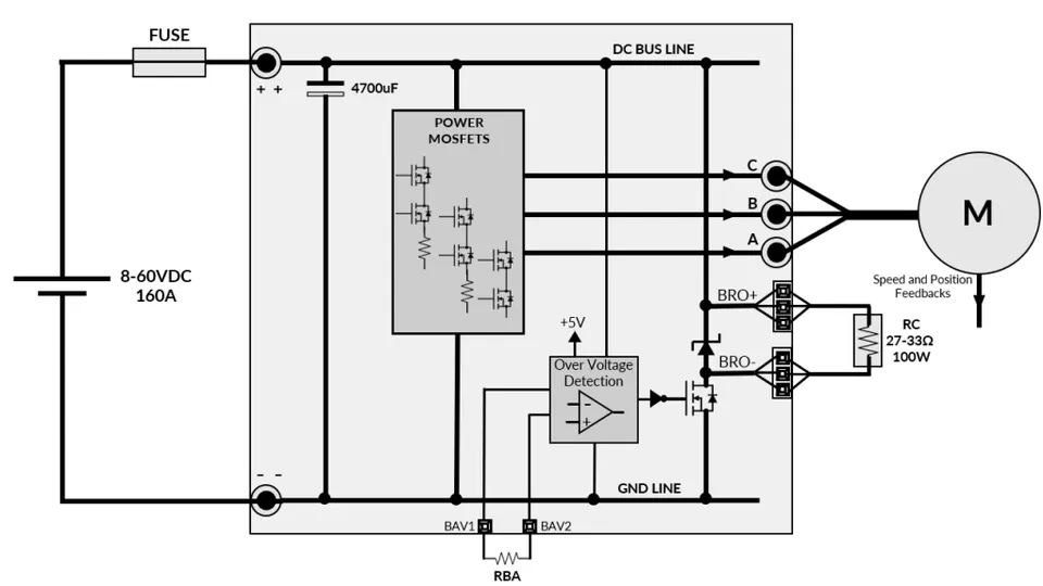
Sample activation voltages are performed in the table below, they are based on the nominal DC bus voltage, however any arbitrary voltage down to 10V can be achieved using a specific formula, to learn more about this please refer to the user manual.
The brake activation voltage should be always above the nominal applied DC BUS voltage to the system to avoid power dissipations on “RC” resistor once not necessary, it’s always better to test the activation voltage by looking at “B1” LED and verify if the LED turns on at the desired value before committing the Motor to the controller.
| 58V | 48V | 36V | 24V | 12V | |
|---|---|---|---|---|---|
| Possible Desired Brake Activation Voltage(approximately) | 61V | 50V | 40V | 26V | 14V |
| "RBA" resistance value [kΩ] (approximately) | ∞(open) | 800 | 314 | 114 | 39 |
Table 1: Examples of “RBA” resistance selection based on desired brake activation voltage
The resistor values for “RBA” should be chosen as close as possible to the theoretically calculated values to have the highest resolution possible in Brake activation.
The schematic of how the Active Brake Chopper was utilized with the Solo Mega is presented below.

J9: Safe Torque Off
The “Safe Torque Off” (STO) is a hardware level protection that safely disconnects the motor from electronics causing the Motor to stop naturally. This is an internal SOLO MEGA safety feature used to stop the motor.
STO could be done in several ways, one of those is the connection through an external relay using internal +5V non- isolated supply voltage and GND:

As it shown in Figure above the +5V internal non-isolated voltage is used to wiring up STO inputs. The safety relay can be commanded from external commanding devices, as for example other relays, safety buttons or toggle switches.
In the winch control diagram STO is controlled by another relay, which is operated by the relays Rewind and Unwind, connected to the buttons. The schematics of how STO wiring is done in the Winch Control Box is provided below:

The pins which are used in the diagram are listed below:
- STO1+: STO channel 1 positive input (optically isolated)
- STO1-: STO channel 1 negative input (optically isolated)
- STO2+
channel 2 positive input (optically isolated) - STO2-
channel 2 negative input (optically isolated) - +5VDC ISO: Non isolated +5V/1A external supply
- GND ISO
isolated ground of SOLO
This external 24VDC relay called “STO” is operated by other relays as it will be fully explained below. The relay provides independent connection of STO1- and STO2- with shared Isolated GND of SOLO MEGA in order to ensure the motor operating conditions, which must be allowed only while the button Rewind Or Unwind is pressed.
To know more about STO please refer to our website or SOLO MEGA User Manual.
Entire wiring diagram
The complete wiring diagram for the winch control box is shown as a combination of these sample schemes, which we used in this article to explain the unit’s control logic. Additional components were incorporated to complete the unit’s structure and ensure it is practical, functional, and safe. The real control box image is provided below.


- The Reed Safety Contact must be included in this scheme as a necessary safety element. It should be placed in the winch manual crank connector to ensure it gets disconnected when the manual crank is in position. This disconnection deactivates the entire control scheme by cutting the supply voltage of +24VDC through the “Safety” relay.
- Another additional element in the scheme is the “Brake” relay. This relay ensures that every time we want the winch motor to operate, the brake is deactivated. The brake functions as a Normally Closed system, remaining in a locked position unless we supply 24VDC to its coil. The relay controls this process by supplying the necessary voltage to the brake.
- The inner system DC/DC converter is represented by a green square element. This device converts the main voltage of 48VDC, required for the motor controller, into 24VDC, which is commonly used in industrial electronics.
The Logic of the System’s Operation
The entire system is operated by the boat deck buttons or a remote control system that functions in parallel with these buttons, as explained below:
- When the system is on and the Reed contact is in its active position (indicating that the manual crank is not engaged with the winch), all the relays are ready to operate.
- If the Rewind button (or its equivalent on the remote control) is pressed, the Rewind relay activates. This provides activation signals to the STO and Brake relays, enabling the motor to start.
- Relay DIR+ is not active in this case, which means that the motor spins in its standard direction, as calibrated during the motor calibration process.
- Relay S/T is also not active in this case, allowing the NC contact to provide a full +12VDC to its S/T pin on J3, corresponding to the motor’s full speed.
- When the Rewind button (or its equivalent on the remote control) is released, the signals are removed from these relays, and the system returns to its “Ready” position.
- If the Unwind button (or its equivalent on the remote control) is pressed, the Unwind relay activates. This provides activation signals to the STO, Brake, S/T, and DIR+ relays, enabling the motor to start in the opposite direction with +6VDC supplied to the speed limit pin, which means the motor begins its rotation at half of the full speed reference.
Safety features of the Winch Control Box
The safety features of this control box are primarily designed to prevent spontaneous motor activation and ensure system readiness while the winch is operated manually. These features are explained in the text of this article and are also listed and summarized below:
- Safe Torque Off: An internal SOLO MEGA safety feature used to stop the motor. This is a hardware level protection that safely disconnects the motor from electronics causing the Motor to stop naturally. In this project STO is connected to a relay which is controlled by the system.
- Reverted Connection of Rewind and Unwind buttons: To prevent simultaneous activation, the buttons are wired through the Normally Closed (NC) contacts of the opposite relay. Thus, the Rewind button is powered through the NC contact of the Unwind relay, and the Unwind button through the NC contact of the Rewind relay. This setup ensures that when one relay is active, the other cannot be activated, as its power supply is disconnected. This safety feature prevents both control buttons from being pressed at the same time.
- Reed Safety Contact: Placed in the winch manual crank connector to ensure it gets disconnected when the manual crank is in position. This disconnection deactivates the entire control scheme by cutting the supply voltage of +24VDC through the “Safety” relay.

Conclusion
Winches have evolved from simple manual tools to sophisticated automated systems, offering enhanced control, power, and versatility across various applications. Whether for off-roading, marine, or industrial use, understanding the range of options and features available can help to select the perfect winch.
In conclusion, SOLO Motor Controllers is dedicated to supporting customers across industries with motor controller expertise. Contact us to support your project needs today.
Related articles

Python on Raspberry Pi: Production Motor Control Tips with SOLO
Production tips for Python motor control on Raspberry Pi with SOLO: SoloPy setup, robust serial/CAN, threading, error recovery and reliable deployment.

EtherCAT Motor Control with the SOLO SOM
How EtherCAT motor control works with the SOLO SOM: CoE and CiA 402, distributed clocks, cyclic synchronous modes and wiring a deterministic servo network.

Cogging Torque vs Torque Ripple: What Is the Difference
Cogging torque vs torque ripple explained: what causes cogging, how it differs from torque ripple, when each matters, and how FOC and design reduce them.
