
Test Bench for Gearbox and Gearmotor Validation
Introduction
A gearbox can swallow 5 to 30 percent of the power a motor delivers, and none of that loss shows up when you test the motor alone. Add backlash, gear noise, and a ratio that may not match the spec sheet, and the motor curve you trust tells you almost nothing about the unit that ships.
This guide shows you how to validate a gearbox or a gearmotor on a test bench. You will see what to measure, how to set up the drive and the load, and which protocols catch the problems before the field does.
Why Gearboxes Need Their Own Test Approach
A bare motor has one shaft, one torque, one speed. A gearbox sits between two shafts and changes all three. It trades speed for torque by its ratio, and it loses some power to friction and churning along the way. A gearmotor is the motor and gearbox built as one unit, so the output you care about is the gearbox output, not the motor shaft.
That changes what a good test looks like. You now have an input side and an output side, and the interesting numbers live in the difference between them. Efficiency is input power minus output power. Ratio is input speed over output speed. Backlash is the small angle the output can move while the input stays still. None of these exist for a motor alone, so a motor bench setup will miss them unless you plan for both shafts.
Gear meshing also adds its own signature. It generates noise and vibration at the gear mesh frequency, and it heats the lubricant under load. A reducer that passes a quick spin test can still run hot, whine, or lose teeth after a few hundred hours. As a rule, treat the gearbox as a system with its own failure modes, not as a passive coupling on the motor.
Takeaway: a gearbox has two shafts and its own losses, so it needs a test that watches both ends.
What to Measure
Five things tell you whether a gearbox or gearmotor is good: torque and efficiency, ratio, backlash, and noise. Here is what each one means and why it matters.
| Quantity | What it tells you | Typical concern |
|---|---|---|
| Input vs output torque | The real torque multiplication and the loss | Efficiency below spec |
| Efficiency | Power lost to friction and churning | Heat, wasted energy |
| Gear ratio | The actual reduction versus the rated one | Wrong gear set, assembly error |
| Backlash | Lost motion at the output | Poor positioning, control instability |
| Noise and vibration | Mesh quality and bearing health | Field complaints, early wear |
Input vs Output Torque and Efficiency
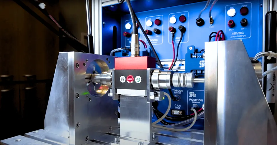
Put a torque sensor on the input shaft and a second one on the output shaft, and read speed at both ends. Input power is input torque times input speed. Output power is output torque times output speed. Efficiency is output power divided by input power, usually given as a percent.
Efficiency is not one number. It changes with load and speed, so you sweep both and build a map. A worm gearbox may sit near 70 percent, while a good planetary unit runs past 90 percent. Test efficiency at the operating points that matter for your application, not just at full load.
Gear Ratio Verification
The rated ratio and the built ratio do not always agree. Drive the input at a steady speed and read the output speed with an encoder. The ratio is input speed over output speed. A clean way to do it is to turn the input a known number of turns and count output turns. A ratio that is off usually means the wrong gear set went in, so this simple check catches assembly errors fast.
Backlash and Lost Motion
Backlash is the play between the gear teeth. It shows up as a small output rotation that happens while the input is held still. To measure it, lock the input shaft, apply a small torque to the output in one direction, mark the angle, then reverse the torque and mark again. The angle between the two marks is the backlash, usually given in arc-minutes or degrees. Backlash matters most for positioning jobs like robotics and CNC, where lost motion turns into position error.
Noise and Vibration
Gear noise points straight at mesh quality. Mount an accelerometer on the housing, or use a microphone, and record while the gearbox runs under load. A spectrum that peaks at the gear mesh frequency and its harmonics tells you how the teeth engage. Rising vibration over an endurance run is an early warning of wear. This is a basic NVH check, and it often catches a bad unit before any tooth actually fails.
Takeaway: measure both shafts, then add backlash and an NVH check that a motor test would skip.
Setting Up the Bench
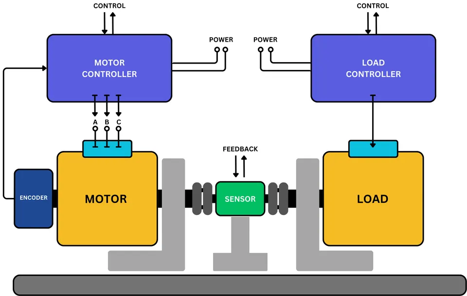
A gearbox test needs something to drive the input and something to load the output, with both shafts instrumented and aligned.
Driving Motor and Loading the Output
You drive the input with a motor under closed-loop control, so you can hold a steady speed or sweep through a range. On the output you apply a controlled load. The load can be an active dynamometer, which is a second motor that absorbs and can also drive, or a passive brake. The active type lets you test both directions and back-driving, while a brake is simpler for fixed load points. Choosing the load type is its own decision, and the trade-off between active, passive, and brake loads depends on your tests and budget.
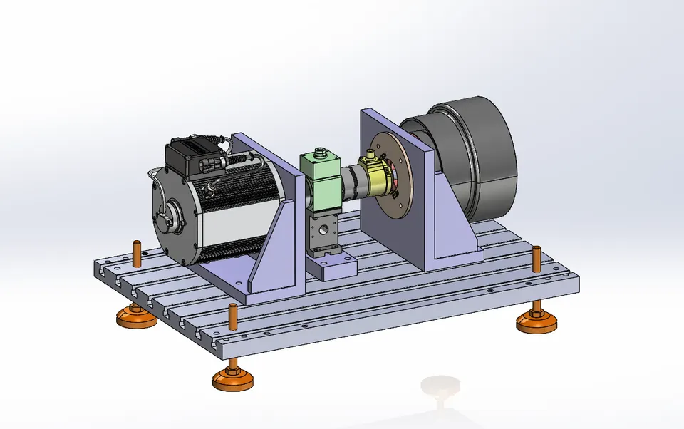
For a gearmotor, the motor is already the input, so you only add the output load and the output sensors. For a bare gearbox, you supply the driving motor too. Put a torque sensor and a speed sensor on each shaft so you can compute efficiency directly.
Mounting and Alignment
Alignment matters more for gearboxes than for a single motor. A misaligned coupling adds side loads that corrupt your torque reading and wear the bearings. Use flexible couplings, and check shaft alignment with a dial indicator or a laser tool before you run.
The housing also has to be held against the reaction torque. A reducer multiplies torque, so the case wants to twist hard against its mounts. Bolt it to a rigid plate or fixture rated above the output torque. A loose or springy mount shows up as noise in the data and, in the worst case, a fixture that moves under load.
Takeaway: instrument both shafts, align the couplings, and clamp the housing against reaction torque.
Test Protocols
Run the tests in an order that builds confidence and protects the unit.
Start with a run-in. New gears need a break-in period at light load and moderate speed, often 30 to 60 minutes, to seat the teeth and circulate lubricant. Skipping run-in inflates the friction you measure and can damage a fresh unit.
Next, verify the ratio with the speed check above, since a wrong ratio makes every later test meaningless. Then run an efficiency sweep. Step through a grid of load and speed points, hold each one until torque and speed settle, and log input and output power. The result is an efficiency map across the operating range, which is far more useful than a single full-load figure.
Run the backlash test cold, before the gearbox warms up, because clearances change with temperature. Record the value as your reference. Finally, log noise and vibration during the efficiency sweep so you capture them across the full range, not just at one point. Save raw channels with timestamps so you can replay any point later.
Takeaway: run-in, then ratio, efficiency map, backlash, and NVH, in that order, with everything logged.
Endurance and Thermal Considerations
A short bench session proves the gearbox works today. It does not prove it survives. Wear is gradual: tooth surfaces fatigue, lubricant breaks down, and backlash grows. To see that, you run the unit for hours or days at representative load and watch the trend.
Temperature is the signal to watch. Friction turns into heat, and that heat lives in the oil or grease. Most lubricants have a temperature limit, and crossing it thins the film and speeds wear. Log housing and lubricant temperature through the run, and compare backlash before and after to catch wear. A full endurance and thermal plan, with cycle profiles and pass criteria, is a topic of its own, so treat this section as the reason to build one, not the plan itself.
Takeaway: long runs plus temperature and backlash trends reveal wear that a quick test hides.
How SOLO Configures Gearmotor Benches
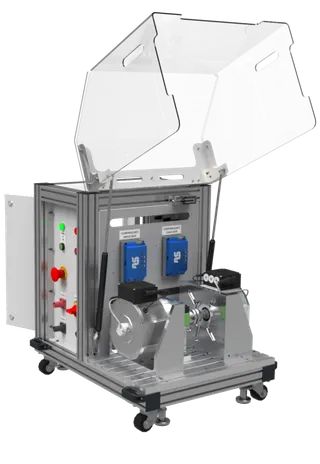
At SOLO we build motor and gearmotor test benches around the controllers we make, and we customize them to your unit at any level, from the driving motor and the output load to the sensors, protocols, and report. A standard bench fits one envelope of power, ratio, and torque, while gearboxes vary widely, so we support two-shaft setups with input and output torque sensing, ratio and backlash checks, efficiency mapping, and logging over CANopen or EtherCAT. The aim is a bench that matches your gearmotor, not one you design around. You can see the current SOLO motor test bench and tell us your specs.
Conclusion
Validating a gearbox means watching two shafts, not one. You measure input and output torque to get efficiency, verify the real gear ratio, check backlash for positioning jobs, and log noise and vibration for mesh quality. Set up a driving motor on the input and a controlled load on the output, align the couplings, and clamp the housing against reaction torque. Run the protocols in order, run-in first, then ratio, efficiency map, and backlash, and add an endurance run with temperature logging to expose wear. If you want a bench shaped around your own gearmotor, the SOLO test bench page is a good next step, and our team can review your specs.
FAQ
How do I measure gearbox efficiency on a bench?
Put a torque sensor and a speed sensor on both the input and the output shafts. Compute input power as input torque times input speed, and output power the same way. Efficiency is output power divided by input power. Sweep load and speed to build an efficiency map, since efficiency changes across the operating range.
How is backlash measured?
Lock the input shaft, apply a small torque to the output in one direction, and mark the angle. Reverse the torque and mark again. The angle between the two marks is the backlash, usually reported in arc-minutes or degrees. Measure it cold, because clearances shift with temperature.
Do I need a dyno on both input and output?
You need a driving motor on the input and a controlled load on the output, with a torque and speed sensor on each shaft. For a gearmotor the motor is already the input, so you add only the output load and sensors. For a bare gearbox you supply the driving motor as well.
Can the same bench test the gearmotor as a unit?
Yes. For a gearmotor you skip the separate driving motor and run the built-in motor as the input. You instrument the output shaft for torque, speed, and backlash, then run the same efficiency, ratio, and endurance tests on the complete unit.
Tags:GearboxGearmotorTest Bench
Products in this article
Related articles
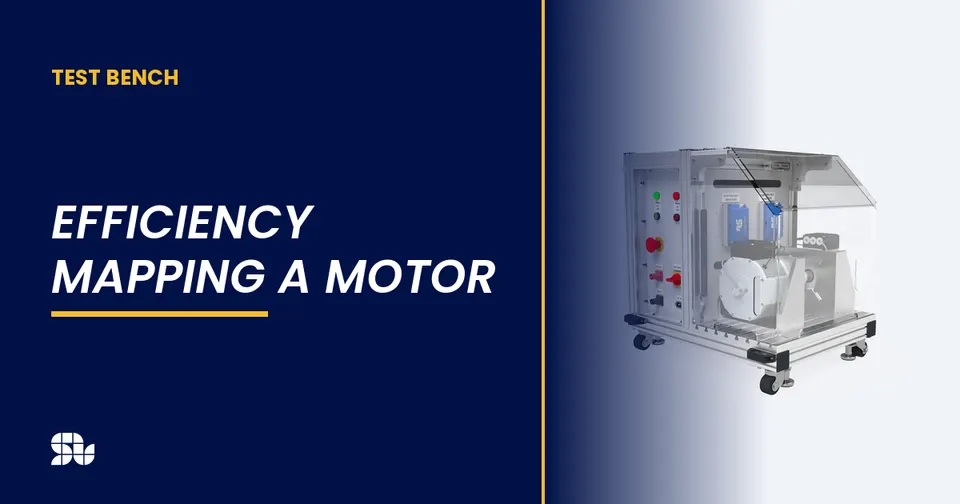
Efficiency Mapping a Motor: Method and What It Reveals
How to build a motor efficiency map on a test bench: the measurement method, the torque-speed grid, and what the map reveals about a motor.
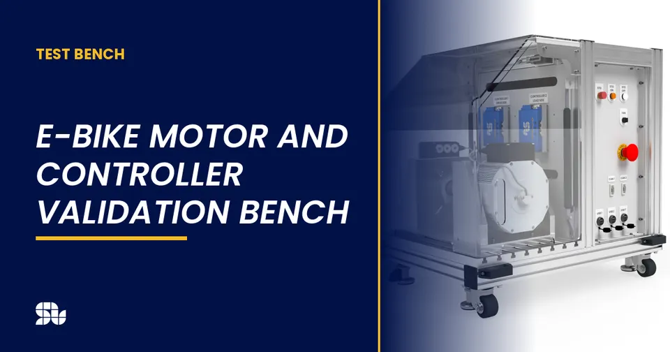
E-Bike Motor and Controller Validation Bench
How to validate an e-bike motor and controller on a bench: torque and cadence, assist profiles, regen and the metrics that matter for e-bikes.

Robotics Actuator Testing: Validating Motors for Robots
How to validate motors and actuators for robots on a test bench: torque density, backlash, repeatability and the metrics that matter for robotics.
