
Hall Sensor Commutation Setup for BLDC and PMSM on SOLO

Introduction
Three hall sensors give a brushless motor only six valid states per electrical revolution, one every 60 degrees. Get that map wrong and the motor stutters, vibrates, or loses torque from a standstill. This guide shows how to set up hall sensor commutation for BLDC and PMSM motors on SOLO, from the six hall states to sequence calibration and feedback selection.
Hall commutation is the simplest way to start a brushless motor with torque from zero speed. The controller reads the rotor position in coarse steps and energizes the right phases for each step. Set the sequence once, and the motor turns smoothly in the direction you expect.
How Hall Sensors Commutate a BLDC/PMSM
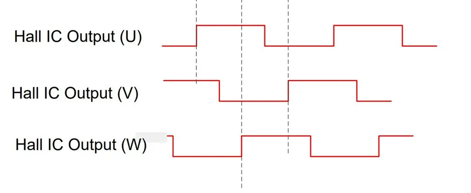
A brushless motor has no brushes to switch the current, so the controller has to do it. To switch at the right moment, it needs to know where the rotor is. Three hall effect sensors, spaced around the stator, report which 60-degree sector the rotor is in. Each sensor outputs a digital high or low, so three sensors give a 3-bit code.
That code is what makes hall commutation work. The controller reads the three bits, looks up which two phases to drive, and energizes them. As the rotor turns, the code changes and the controller moves to the next phase pair. This is why hall sensors let a motor produce torque from a dead stop, with no guessing about rotor angle.
The Six Hall States and Commutation Sequence
Three hall sensors can in theory output eight codes, but two of them, all-zero and all-one, never happen on a correctly placed sensor set. That leaves six valid states. Each state covers a 60-degree slice of the electrical cycle, and together the six slices cover a full 360 electrical degrees.
The commutation sequence is the fixed order these states pass through as the rotor spins. For each state, the controller drives a specific phase pair, so the magnetic field always pulls the rotor forward.
| Hall state (HA HB HC) | Electrical sector | Action |
|---|---|---|
| 1 0 1 | 0 to 60 degrees | drive phase pair 1 |
| 0 0 1 | 60 to 120 degrees | drive phase pair 2 |
| 0 1 1 | 120 to 180 degrees | drive phase pair 3 |
| 0 1 0 | 180 to 240 degrees | drive phase pair 4 |
| 1 1 0 | 240 to 300 degrees | drive phase pair 5 |
| 1 0 0 | 300 to 360 degrees | drive phase pair 6 |
The exact bit pattern per sector depends on how the sensors are mounted and wired, which is why the sequence is calibrated, not assumed. The takeaway: six states, six phase actions, repeated every electrical cycle.
Hall Commutation vs Sinusoidal Feedback
Hall sensors give a coarse position signal, updated only six times per electrical cycle. That is enough to commutate a motor and run six-step or trapezoidal control, where torque has some ripple by design. It is the cheapest and most rugged feedback option.
Sinusoidal control, like field oriented control, needs a continuous angle, not six steps. For that you usually want an encoder or a sensorless estimator. Hall feedback can still seed a sensorless startup, then hand over at higher speed. To choose between sensored and sensorless operation for your application, see sensor vs sensorless. The takeaway: halls are great for commutation and low-cost feedback, but they are coarse compared to a fine encoder.
Setting Up Hall Feedback in Motion Terminal
In the SOLO Motion Terminal you tell the controller to use hall sensors as the feedback source. Once hall feedback is selected, the controller reads the three hall lines and uses the state map for commutation. The setup has two parts that matter most: the motor pole count, and the hall sequence itself.
Before you start, the motor must be wired correctly. This article covers the commutation setup, not the cabling. For the hall signal wiring and pinout to a SOLO board, follow hall sensors to SOLO for controlling speed and torque.

Configuring Motor Poles for Correct Hall Timing
Hall timing is electrical, but the motor turns in mechanical degrees. The link between the two is the pole count. A motor with more poles goes through more electrical cycles per mechanical turn, so the hall states repeat more often per revolution.
If the pole count is wrong, the commutation timing drifts against the real rotor position. The motor may still spin, but with rough torque or reduced speed. So set the number of poles to match your motor before you calibrate the hall sequence. Set this value first, because the calibration below assumes the controller already knows how many electrical cycles make one mechanical turn.
Calibrating the Hall Sequence
Calibration aligns the state-to-phase map with your actual sensor mounting and wiring. The Motion Terminal runs a short routine: it moves the rotor, records which hall state appears at each position, and stores the order. After that, the controller knows exactly which phase pair to drive for each of the six states.
You only do this once per motor and wiring setup. If you swap motor phase leads or hall wires, run it again. A clean calibration is what turns the raw hall states into smooth, repeatable commutation in the right direction.
Verifying Commutation
After calibration, check the motor at low speed, where commutation errors show up first. Command a slow, steady rotation and watch for even motion. Smooth, quiet turning with steady current means the sequence is right.
Watch for these signs of a good setup:
- The motor starts cleanly from a standstill in the commanded direction.
- Torque feels uniform through a full turn, with no periodic kick.
- Current stays steady at constant speed, without regular spikes.
If you can log signals, watch the phase current and the hall states together at low speed. A regular, repeating pattern is what you want. The takeaway: low speed is your best test, because a bad state map produces visible jerks there before it smooths out at higher RPM.
Troubleshooting Hall Commutation
Most hall commutation problems trace back to a wrong sequence or a noisy signal. If the motor stutters, vibrates, or runs hot, work through these first.

- Motor jerks or refuses to start: the state-to-phase map is likely wrong. Re-run the hall sequence calibration. A swapped pair of hall wires or motor leads is the usual cause.
- Spins the wrong way: the sequence direction is reversed. Recalibrate, or correct the phase or hall wiring order, then calibrate again.
- Rough torque or random twitching: often electrical noise on the hall lines, which can flip a state bit and trigger a false commutation. Filtering helps here. See manage noisy encoders or hall sensors for active noise filtering.
- Weak torque at start, fine once moving: usually a pole count mismatch. Confirm the number of poles matches the motor.
If two faults appear together, fix the wiring order first, then recalibrate, then address noise. The takeaway: a stuttering motor with hall feedback is almost always sequence or noise, and both are fixable in setup.
How SOLO Supports Hall Commutation
SOLO controllers support hall sensor feedback for BLDC and PMSM motors, with a guided calibration routine in the Motion Terminal that maps the six hall states to the right phase actions for you. The same controllers also handle encoder feedback and sensorless operation, so you can start on halls and move to finer feedback later without changing hardware. You can explore the supported feedback options across our motor controllers, and run the setup from the SOLO Motion Terminal.
Conclusion
Hall sensor commutation reads the rotor in six coarse states and drives the matching phase pair for each one, which is what lets a brushless motor make torque from a standstill. To set it up well, select hall feedback, set the pole count to match your motor, then run the sequence calibration so the state-to-phase map fits your wiring. Verify at low speed, where errors show first, and treat stutter as a sequence or noise problem. When you are ready to configure your motor, open the SOLO Motion Terminal and walk through the hall calibration.
FAQ
How do hall sensors commutate a brushless motor?
Three hall sensors report which 60-degree sector the rotor is in, giving six valid states per electrical cycle. For each state, the controller drives a specific pair of motor phases so the field pulls the rotor forward. As the rotor turns, the hall code changes and the controller steps to the next phase pair, which keeps torque flowing from a standstill up through normal speed.
Why does my motor stutter or vibrate with hall feedback?
The usual cause is a wrong commutation sequence, so the controller drives the wrong phase pair for a given hall state. Re-run the hall calibration to fix the state-to-phase map. If the motion is rough and irregular rather than steady, suspect electrical noise on the hall lines flipping a state bit, and apply noise filtering.
Do I need the number of poles right for hall commutation?
Yes. The pole count links the electrical timing of the hall states to the mechanical rotation of the motor. If it is wrong, commutation timing drifts against the real rotor position, which generally shows up as weak starting torque or rough running. Set the number of poles to match your motor before you calibrate the hall sequence.
Hall sensors or encoder: which feedback should I use?
Hall sensors are low cost and rugged, and they are enough for commutation and six-step control. An encoder gives a continuous, fine angle, which sinusoidal and field oriented control need for smooth torque. Many setups start on halls and add an encoder or sensorless estimation later. See sensor vs sensorless to weigh the trade-off for your application.
Related articles
Stall Detection and Motor Protection Setup on SOLO
Set up stall detection and motor protection on SOLO: configure the stall time, current and fault response to protect your motor from a locked rotor.
PWM Frequency Selection for Low-Inductance Motors
How to choose the PWM switching frequency on SOLO, why low-inductance motors need a higher frequency, and the trade-offs with heat and ripple.
Open-Loop Manual Mode: Spinning a Motor with Potentiometers
How to spin a motor in open-loop manual mode on SOLO with potentiometers and no programming. When open loop is enough, and its limits.
