
Robotics Actuator Testing: Validating Motors for Robots
Introduction
A robot joint that repeats its position within 0.05 degrees on the bench can drift past 0.5 degrees in the field once backlash and thermal drift show up. That gap is the whole reason for robot actuator testing. A joint that looks fine at low speed can lose accuracy, lag the command, or overheat once it carries a real arm.
This guide shows you how to validate a robot actuator on a test bench, and which metrics actually decide if the joint is good. We cover torque density, repeatability, backlash, and dynamic response, then how to set the bench up and log the data you need.
What Makes Robot Actuators Different to Test
A robot actuator is not a bare motor. It is a motor plus a reduction plus feedback, packaged to move a joint. Most modern joints use a frameless BLDC or PMSM motor, a high-ratio gearbox such as a strain-wave or cycloidal drive, and a position sensor on the output. The job is not raw speed. It is torque density and accurate position control at low speed.
That changes what you test. A fan motor is judged mostly on efficiency at one operating point. A robot joint is judged on how faithfully it holds and tracks a position under a changing load. So the bench has to measure position and torque together, with enough resolution to see small errors, and it has to do it repeatedly.
Takeaway: test the actuator as a joint, not as a motor, with position and torque measured together.
Key Metrics for Actuator Validation
A handful of numbers decide whether a joint is ready. Here they are before the detail.

| Metric | What it tells you | Why it matters for a joint |
|---|---|---|
| Torque density | Torque per unit mass or volume | A heavier joint loads every joint above it |
| Peak vs continuous torque | Burst capability vs steady duty | A joint sized only for peak overheats in service |
| Position accuracy | Error between command and true position | Sets how precisely the robot reaches a point |
| Repeatability | Spread when returning to the same point | The number most robot specs live or die on |
| Backlash | Lost motion on direction reversal | Causes play and limits fine control |
| *Bandwidth | How fast the joint tracks a command | Decides how snappy and stable the motion is |
Torque Density and Peak vs Continuous Torque
Torque density is torque per unit mass, and it is the headline number for a joint. Every actuator carries the ones above it in the kinematic chain, so a heavy joint costs you payload everywhere. On the bench you load the output and measure the torque the joint can hold at a given mass.
Then separate peak from continuous torque. Peak is the short burst the joint can deliver for a second or two, useful for acceleration. Continuous is what it can hold for minutes without overheating. A joint specified only on peak will look strong and then thermally fault in real duty. Measure both, and log the winding temperature while you do.
Position Accuracy, Repeatability and Backlash
For most robots, repeatability matters more than absolute accuracy. Accuracy is how close the joint gets to the true commanded angle. Repeatability is how tightly it returns to the same point over many tries. You measure both by commanding a set of positions, reading the output sensor, and recording the spread.
Backlash is the lost motion when the joint reverses direction, mostly from the gearbox. To measure it, hold the output, drive the input back and forth across zero load, and read the dead band on the output sensor. The gearbox choice drives this result, so treat the reduction stage as its own line item when you compare drives.
Bandwidth and Dynamic Response
A joint also has to move fast and settle cleanly. Bandwidth is how high a command frequency the joint can follow before it falls behind. You test it two ways: a step response, where you command a sudden move and watch the rise time, overshoot, and settling, and a frequency sweep, where you increase command frequency until the output amplitude drops. Both reveal resonances and a soft transmission.
This is where the controller matters. A tight current loop and a well-tuned position loop set how much usable bandwidth the joint really has. A capable bench drives the actuator with a controller that exposes those loops, so you measure the joint and the control together, the way it will run in the robot.
Takeaway: torque density and repeatability rank the joint, while bandwidth tells you if it can move at speed.
Setting Up the Bench for Actuators
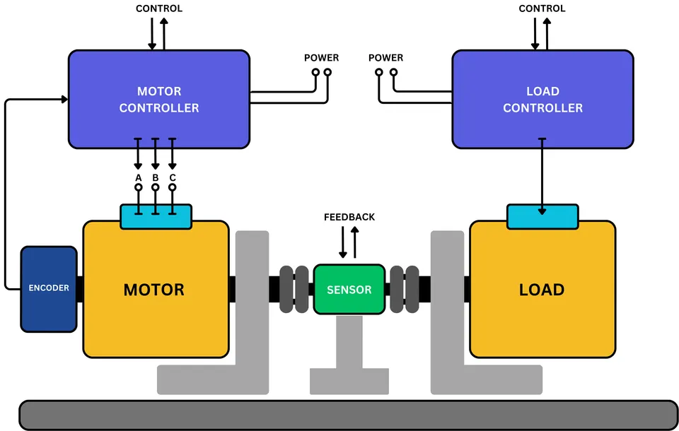
A robot actuator test bench couples the actuator output to a controllable load, then logs position, torque, current, and temperature while you run a profile. The setup needs more care than a bare motor because the output is geared and slow, with high torque and small angles.
Mounting Frameless and Geared Actuators
Mounting decides your data quality. A frameless actuator ships as a separate rotor and stator, so the bench fixture has to provide the bearings, the alignment, and the housing the motor would otherwise lack. Get the air gap and concentricity right, or the torque reading drifts.
A geared actuator is easier to mount as a unit, but you couple to the slow, high-torque output, so the torque sensor and coupling must be rated for that output torque, not the motor torque. Keep the coupling stiff, since a soft coupling hides backlash and corrupts the bandwidth test. The reduction stage itself is a topic of its own, so size the output sensor to the geared torque before you start.
Loading Strategy
The load has to behave like the joint’s real world. For a robot joint that often means an active load, a second motor that can both resist and back-drive, so you can mimic gravity on an arm or a reaction torque. A simple brake only absorbs, which is fine for steady torque points but cannot reproduce a load that pushes back. Pick the load to match the tests you run, since the choice between an active dyno and a brake sets what you can reproduce.
Takeaway: mount for alignment and a stiff output coupling, then load with a dyno that can push back when the test needs it.
Control and Integration for Robotics
A robot joint never runs alone, so the bench should test it the way the robot will drive it. That means real fieldbus control, multi-axis coordination, and clean data logging.
Most robot stacks talk over CANopen with the CiA 402 motion profile, or over EtherCAT for tighter timing, and many research robots run on ROS2 above that. A bench that speaks the same protocols lets you command the actuator through the same path the robot uses, so you validate the joint and its interface together. If you drive your robots from ROS2, our overview of ROS2 for motor controllers shows how the control node fits.
Multi-axis matters too. A bench that can run several actuators at once, time-synchronized, lets you test a whole arm’s worth of joints under a coordinated profile, not one joint in isolation. Log every channel with timestamps so you can replay a run and compare units. Without that, every test turns into manual note-taking.
Takeaway: drive the joint over its real protocol and log every axis, so the bench test matches the robot.
Endurance and Thermal Considerations
A robot joint cycles millions of times over its life, so a single pass tells you little. Endurance testing runs the joint through repeated motion cycles and watches the metrics drift. Backlash usually grows, repeatability widens, and friction climbs as the gearbox wears. The bench should rerun the same accuracy and backlash checks at intervals so you can plot the trend, not just a pass or fail.
Heat is the other limit. Continuous torque is set by how fast the winding heats, and a joint buried in a tight housing has little room to shed it. You log winding and housing temperature across a duty cycle to find the real continuous rating. The detailed method for thermal and endurance runs is its own subject, so plan a dedicated thermal profile rather than reading it off a single short test.
Takeaway: cycle the joint and track how backlash, repeatability, and temperature drift over time.
How SOLO Validates Robotics Actuators
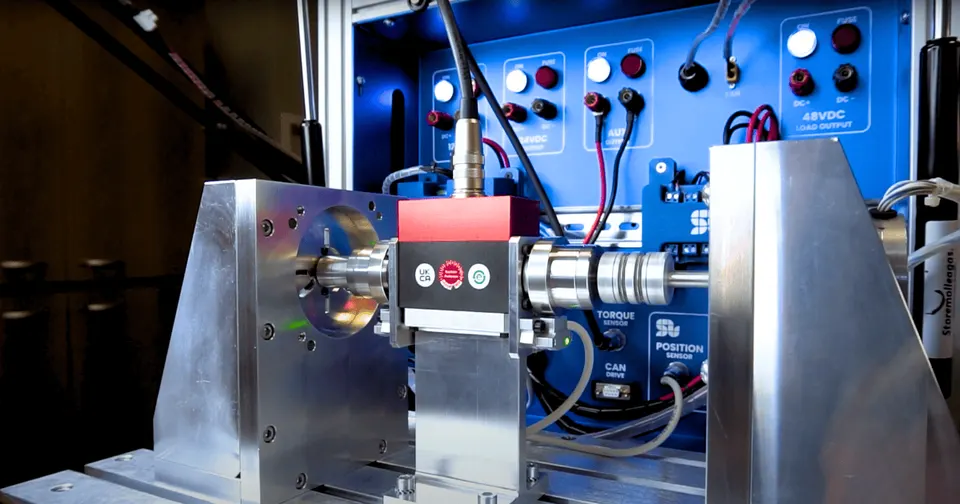
At SOLO we build benches that test robot actuators as joints, not just motors. We support frameless and geared BLDC and PMSM actuators on one bench, with the active or brake loading the test needs, plus torque, position, and temperature sensing logged together. Because the bench runs on the same SOLO controllers you would put in the robot, you measure position accuracy, repeatability, backlash, and bandwidth with a real FOC current loop underneath, over CANopen or EtherCAT. We customize the bench to your actuators at any level, from the fixture and the sensor range to the protocol and the report. You can see the current SOLO motor test bench and tell us your joint specs.
Conclusion
Validating a robot actuator means testing it as a joint, with position and torque measured together. The metrics that decide a joint are torque density, peak versus continuous torque, position accuracy, repeatability, backlash, and bandwidth, so size the bench and sensors to read all of them. Mount frameless and geared actuators for alignment and a stiff output coupling, load them with a dyno that can push back, and drive them over the same CANopen or EtherCAT path the robot uses. Then cycle the joint to watch backlash and temperature drift over its life. If you want a bench matched to your actuators, the SOLO motor test bench page is a good next step, and our team can review your specs.
FAQ
What should I measure when testing a robot actuator?
Measure torque density, peak and continuous torque, position accuracy, repeatability, backlash, and bandwidth, and log winding temperature throughout. For most robots, repeatability and torque density are the two numbers that rank one joint against another, so give them the most attention.
How do I test backlash and repeatability on a bench?
For backlash, hold the actuator output, drive the input back and forth across zero load, and read the dead band on the output sensor. For repeatability, command the joint to the same position many times and record the spread of the output readings. Both need a high-resolution output sensor and a stiff coupling so the bench does not add play of its own.
Can the bench integrate with ROS2?
A bench that drives the actuator over CANopen or EtherCAT can sit under a ROS2 stack, so you command the joint through the same path the robot uses. The ROS2 layer is a design-ready integration built on those released buses, not a stock package, so it fits robotics projects that already run ROS2. See ROS2 for motor controllers for how the control node connects, and ask us if your setup needs it.
Do I need to test peak torque or continuous torque?
Both, because they answer different questions. Peak torque tells you how hard the joint can accelerate for a second or two. Continuous torque tells you what it can hold for minutes without overheating. A joint sized only on peak often thermally faults in real duty, so always measure continuous torque with the winding temperature logged.
Tags:ActuatorsRoboticsTest Bench
Products in this article
Related articles

Efficiency Mapping a Motor: Method and What It Reveals
How to build a motor efficiency map on a test bench: the measurement method, the torque-speed grid, and what the map reveals about a motor.

E-Bike Motor and Controller Validation Bench
How to validate an e-bike motor and controller on a bench: torque and cadence, assist profiles, regen and the metrics that matter for e-bikes.
Test Bench for Gearbox and Gearmotor Validation
How to validate a gearbox or gearmotor on a test bench: efficiency, backlash, ratio verification, and the load setup gearmotors need.
