
Simple Speed Control of an AC Induction Motor in Analog and Digital Modes Using SOLO (FOC)
AC Induction motors (ACIM) are one the most used types of electrical motors specially in industry, they have a very huge pile of share in how the industry is motorized these days in factories and automations. In these types of motors, there are two main parts contributing in the motions:
1. The Stator, which is the stationary part of the motor, and is in charge of generation of the magnetic field
2. The rotor, which is the rotating part without any physical contact to the stator

In General, the theory of operation of ACIMs is in a way that the stator’s magnetic field will induce a current into the rotor, resulting in Torque generation and mechanical rotation of the rotor. In another word, once a rotating magnetic field is applied on the stator normally using a 3-phase voltages on the the stator with 120 degrees of phase shift with respect to each other, with a speed known as “synchronous speed”, the rotor will try to follow this rotating field with a speed which is called “Actual rotating speed” or the real mechanical speed , and the actual speed is slightly less than synchronous speed. The difference between synchronous speed and actual speed is known as “slip”, which is the main reason that we call these motors Asynchronous Motors.

So despite other types of 3-phase motors with magnets like Brushless DC or Permanent magnet synchronous motors, there is no physical magnet used in the stator of ACIMs, and therefore the stator field intensity is adjustable by controlling the amount of current we inject into the stator (known as magnetizing current), and this phenomenon, gives an extra degree of freedom in control of AC induction motors with respect to permanent magnet counter parts in which the field intensity (flux) is constant and depends on the strength of the magnets used.
There are two main types of AC induction motors based on the formation of their rotor :
1. Squirrel cage type rotor
2. AC induction motors with wound type rotor
The first category of the AC motors however, are more popular among the industry as they are more cost effective and reliable.

AC induction motors are normally controlled with devices called “Variable Frequency Drives” known as VFDs, in which they apply the rotating field on the stator in a controlled manner so the rotor can follow and reach the desired mechanical speed.
There are lots of ways that an AC induction motor controllers can fix the speed of the rotor on desired speed, but the most advanced and reliable ones are normally coming from the Field Oriented Control or Vector Control enabled models. In Field Oriented Control (FOC) enabled versions, the Torque and the stator field ( flux ) are controlled separately, and this gives a huge advantage over normal VFDs as they offer much more reliable and robust control, specially in applications that the mechanical load on the shaft of the motor can vary time to time.
SOLO is using FOC for controlling AC induction motors with a methodology that can be seen below in the diagram. In simple words, SOLO tries to control the speed of ACIM motor using two different control parameters:
1. Controlling speed with regulation of Torque using quadrature current (Iq)
2. Regulation of magnetizing current to control the intensity of stator’s field (flux) using direct current (Id)

Both of the mentioned control parameters above, are accessible to the user, and the user can define the desired value for each of them as can be seen in the following wiring Diagram in its simplest form by using manual (analoge) standalone control mode:
SOLO UNO wiring

SOLO MINI wiring

SOLO BETA wiring

You need to notice that, the mentioned wiring is only one of the possible ways of running the system with SOLO, there are multiple other types of wirings, including sending control references, using PWM pulses or even sending all the commands using only the digital communications with USB or UART protocols.
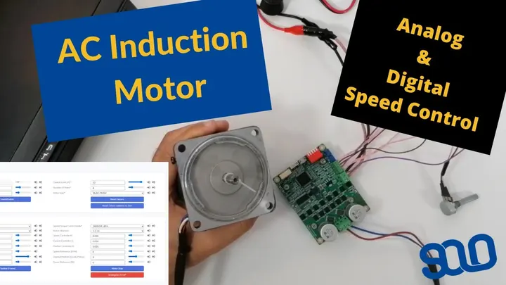
To learn more, you can watch the following video which demonstrates the speed control of an AC induction motor both in fully analog mode using a pair of potentio-meters and later in digital mode, using SOLO Motion Terminal and a single USB cable!
Products in this article


Related articles
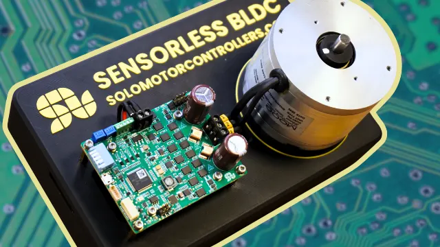
Sensorless Control of Brushless or Permanent Magnet Synchronous Motors in Wide Speed Range
Sensorless control eliminates the need for shaft sensors, reducing cost and improving reliability, here a description of possibility given with this tech

How to Tune a PID Controller for Your Motor Controller
A practical guide to PID tuning for motor control: PID gains, transient response, step-by-step tuning, common problems and FOC considerations for SOLO users.
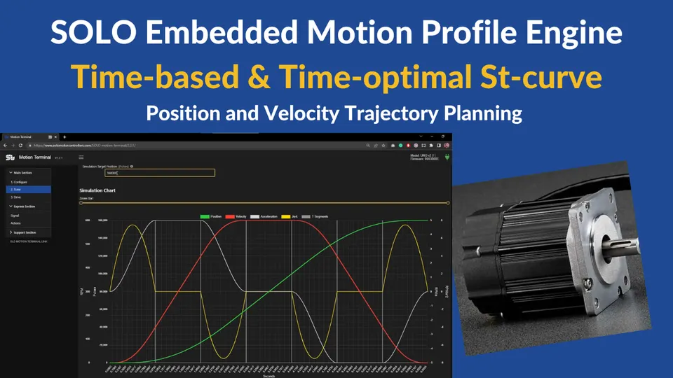
SOLO Embedded Motion Profile Engine
The Embedded Motion Profile Generation Engine that allows its users to simply create smooth and low jerk Position or Speed trajectories
