
Torque Constant (Kt): How SOLO Converts Current to Torque
Introduction
“How many amps do I need for 2 N·m?” is the first question on any drive sizing sheet, and one number answers it. That number is the torque constant (Kt).
The torque constant is the torque a motor produces per amp of current, measured in N·m/A. In a FOC drive, torque = Kt x Iq, so the controller sets torque directly by regulating the quadrature-axis current Iq. Get Kt right and current sizing falls out of simple multiplication.
What Is the Torque Constant (Kt)?
The torque constant tells you how much torque a motor makes for each amp you push into it. Its unit is N·m/A (newton-meters per amp). A motor with Kt = 0.1 N·m/A makes 0.1 N·m for every amp of torque-producing current.
Think of Kt as the exchange rate between current and torque. A higher Kt means more torque per amp, so you reach a target torque with less current and less heat. A lower Kt means you need more current for the same torque. Motor makers set Kt through the magnet strength, the number of turns in each winding, and the rotor geometry.
Kt is usually listed on the motor datasheet. When it is not, you can measure it on a bench: apply a known current, read the torque, and divide. The value stays close to constant across most of the operating range, which is what makes it so useful for sizing.
Takeaway: Kt is torque per amp, in N·m/A. It is the single number that links the current you supply to the torque you get.
The Core Equation: Torque = Kt x Iq
The working relationship in a FOC drive is short:
Torque = Kt x Iq
Here Iq is the torque-producing current, and Kt is the torque constant. Multiply the two and you have shaft torque. Because the equation is linear, doubling Iq generally doubles torque, up to the point where the magnetics start to saturate.

Why Iq and Not Phase Current
You might expect torque to depend on the raw phase current the motor draws. In a FOC drive it does not. Field Oriented Control splits the stator current into two parts in the rotating d-q frame: Id, the field current, and Iq, the torque current. Only Iq makes torque. Id sets the magnetic field and, at normal speed, you hold it near zero.
So the controller does not chase phase current. It regulates Iq, and torque follows. This is why a FOC drive feels like a DC motor: one current knob, one torque output. The same separation is what lets the controller hold steady torque while the phase currents themselves swing as sine waves. For the full picture of how the loop turns Iq into a controlled torque output, see our overview of torque control.

A Worked Example
Numbers make it concrete. Take a motor with Kt = 0.1 N·m/A and command an Iq of 10 A.
| Kt (N·m/A) | Iq (A) | Torque (N·m) |
|---|---|---|
| 0.1 | 5 | 0.5 |
| 0.1 | 10 | 1.0 |
| 0.1 | 20 | 2.0 |
| 0.2 | 10 | 2.0 |
At 10 A you get 1.0 N·m. Need 2.0 N·m from the same motor? Push 20 A, as long as the controller and motor can carry it. Or pick a motor with a higher Kt and reach 2.0 N·m at the same 10 A. That trade between current and Kt is the heart of drive sizing.
Takeaway: Torque = Kt x Iq. The controller commands Iq, and Kt turns it into shaft torque.
Where Kt Comes From (and Ke)
Kt comes from the electromechanical coupling inside the motor: the same magnetic interaction that turns current into force also turns motion into voltage. That second effect is the back-EMF constant (Ke), the voltage a motor generates per unit of speed. To understand the voltage side of this coupling, see how back-EMF builds up as the rotor spins.
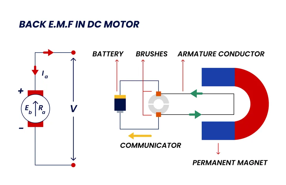
Here is the part that surprises many engineers. In SI units, Kt and Ke are numerically equal. A motor with Kt = 0.1 N·m/A has Ke = 0.1 V·s/rad. They are two views of the same physics, one looking at torque from current, the other at voltage from speed. The catch is units. Datasheets often give Ke in V/krpm and Kt in N·m/A, so the printed numbers look different even though the underlying value is the same. Always convert to SI before you compare them.
Takeaway: Kt and Ke describe one coupling. In SI units they are equal, so a known Ke gives you Kt for free.
Kt in Practice: Sizing Current and Torque
Once you trust torque = Kt x Iq, sizing a drive is mostly arithmetic. You start from the torque the load needs, divide by Kt, and you have the current the controller must deliver.
Continuous vs Peak Torque
The motor’s Kt sets the torque per amp, but the controller’s current limit sets the maximum torque you can actually reach. There are two limits to watch. The continuous current is what the system can carry all day without overheating. The peak current is a short burst, often two to three times continuous, that the controller allows for a few seconds during acceleration or a stall.
So a motor rated for 2 N·m continuous might deliver 5 N·m for a brief peak, if the controller can source the matching peak current. Size for the continuous load, then check that your peak demand fits inside the controller’s peak limit.
What Reduces Effective Kt
Kt is not perfectly constant. At high current the magnetic core starts to saturate, and each extra amp makes less extra torque than the one before. The effective Kt drops, so torque grows slower than the straight-line equation predicts. This is why you cannot assume 100 A gives ten times the torque of 10 A on a motor pushed into saturation.

Temperature plays a part too. Hot magnets lose a little strength, which trims Kt slightly. For most operating points the linear model holds well. Near the peak-current limit, expect real torque to fall a bit below Kt x Iq.
Takeaway: Divide required torque by Kt to get current, then check it against the controller’s continuous and peak limits. Expect Kt to sag near saturation.
Seeing Kt and Iq in SOLO Motion Terminal
SOLO controllers run automatic motor identification, which measures the motor and finds its parameters, including the values that drive the torque calculation. From there the FOC loop applies torque = Kt x Iq for you, with no manual constant to type in. You can watch the live Iq in SOLO Motion Terminal while the motor runs, so the current-to-torque relationship is visible, not just on paper. Any of our motor controllers handles this out of the box.
Conclusion
The torque constant Kt is the torque a motor makes per amp, in N·m/A. In a FOC drive the working rule is torque = Kt x Iq, where Iq is the torque-producing current the controller regulates directly. Kt and the back-EMF constant Ke are the same value in SI units, so one gives you the other. To size a drive, divide the torque you need by Kt to find the current, then check it against the controller’s continuous and peak limits, and remember that Kt sags a little near magnetic saturation. A controller that identifies the motor and runs FOC natively, like a SOLO motor controller, turns that math into a live, controlled torque.
FAQ
How do you calculate torque from current?
In a FOC drive, torque = Kt x Iq. Multiply the torque constant Kt (in N·m/A) by the quadrature-axis current Iq (in A) to get shaft torque in N·m. For example, Kt = 0.1 N·m/A at Iq = 10 A gives 1.0 N·m.
What are the units of the torque constant?
The torque constant is measured in newton-meters per amp, written N·m/A. It tells you how many N·m of torque the motor produces for each amp of torque-producing current.
Is the torque constant the same as the back-EMF constant?
In SI units, yes. Kt in N·m/A is numerically equal to the back-EMF constant Ke in V·s/rad, because both describe the same electromechanical coupling. They often look different on a datasheet only because the units differ, so convert to SI before comparing.
Does the torque constant stay constant at high current?
Not exactly. At high current the magnetic core saturates, so the effective Kt drops and torque grows slower than Kt x Iq predicts. The linear model holds well for normal operation but underestimates the gap near the peak-current limit.
Related articles

Back-EMF Constant (Ke) vs Torque Constant (Kt)
Ke vs Kt explained: what the back-EMF constant and torque constant mean, how they relate, why they are numerically equal in SI units, and how to use them.

Id and Iq: The d-q Frame in Motor Control Explained
Id vs Iq made simple: what the d-q frame is, why Iq produces torque and Id sets the field/flux, and how the d-q axes make FOC controllable in motor control.
Magnetizing Current (Id) for Induction Motors in FOC
How to set the Id magnetizing current for an AC induction motor in FOC on SOLO: what Id does, how to size it, and how it affects torque and heat.
