
Building Your E-Bike: Technology, Design, and Impressions
E-Bikes are the most sustainable urban transportation due to their convenience and efficiency. Accessible and user-friendly, they reduce travel time and parking hassles.E-bikes are energy-efficient, with minimal environmental impact, especially when charged with renewable energy. They alleviate traffic congestion and promote health through moderate exercise. Cost-effective compared to cars, E-Bikes also integrate well with public transportation and bike-friendly infrastructure. Cities investing in bike lanes and aiming for sustainability goals find E-Bikes a perfect fit. Embracing e-bikes helps reduce carbon footprints, promoting greener, healthier urban living.
Electric bikes (E-Bikes) are ideal for individuals with knee pain or disabilities due to their motorized assistance, which reduces physical strain and effort. Riders can adjust the level of motor support to suit their needs, making pedaling easier and less painful.

Picture #1 : Sustainability of E-Bikes
The image above showcases a comparison of different modes of transport based on kilometers traveled per kilogram of CO2 emissions.. Ranked from most to least sustainable, the E-Bike leads at 67 km, followed by the bike at 48 km, bus at 33 km, rail at 25 km, and walking at 18 km. Car travel with two passengers reaches 11 km, international flights 6.5 km, single-passenger cars 5.5 km, and domestic flights only 4 km. This chart highlights the importance of choosing low-emission transportation methods to reduce carbon footprints and promote sustainable travel. Hybrid bikes produce way less carbon footprint compared to buses, trains and even normal bikes.
TYPES OF E-BIKEs
Electric bikes (E-Bikes) come in various types, each catering to different needs and preferences. Popular types include commuter e-bikes, ideal for daily travel with features like fenders and lights; mountain e-bikes, designed for off-road adventures with robust frames and powerful motors; and folding e-bikes, perfect for easy storage and transport. Cargo e-bikes are built to carry heavy loads, making them great for deliveries. Additionally, hybrid e-bikes combine the best features of road and mountain bikes, offering versatility. These diverse e-bike options ensure there’s a perfect choice for everyone, enhancing eco-friendly transportation and making commutes more efficient.
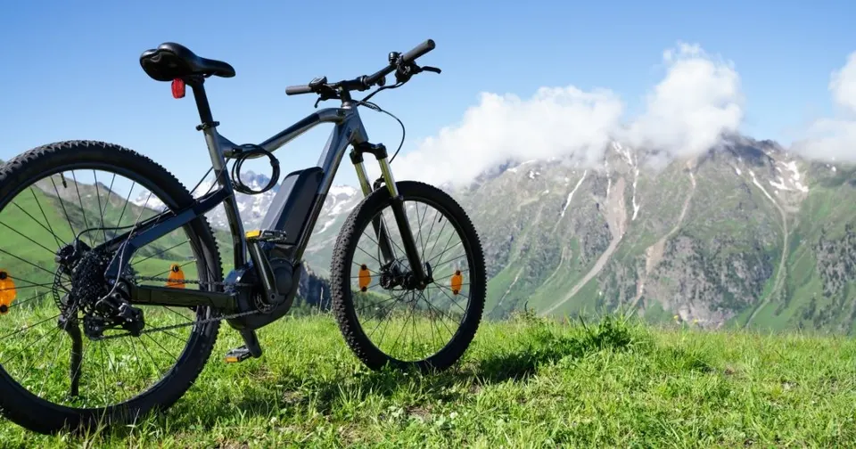
Picture #2 : A mountain E-bike
How Electic Bike Work
An E-Bike, or electric bicycle, is a bicycle equipped with an electric motor that assists with pedaling. Usually the motor is powered by a rechargeable battery, and the level of assistance can usually be controlled by the rider. E-Bikes combine the traditional mechanical aspects of a bicycle with the advantages of electric propulsion, offering an enhanced riding experience.
As you can see in the illustration below the control scheme of an E-Bike includes four key components: the Battery, Controller, Motor Hub, and Torque Crankshaft. We integrated this schematic into the regular bike to transform it into an e-bike.
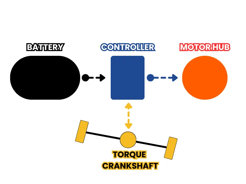
Picture #3 : Schematics of E-Bike
Types of assist in E-Bike
Mainly divided into three types :
- Pedal-Assist : The motor assists only when the rider is pedaling, with various levels of assistance that can be adjusted. The rider still needs to pedal, but the motor makes it easier. It is further divided into two :
- Speed sensor based
- Torque sensor based
- Throttles Assist: The motor can provide power without pedaling, similar to a scooter or motorcycle. The rider can control the speed with a throttle, usually located on the handlebar.
- Hybrid: Combines both pedal-assist and throttle features, allowing the rider to switch between modes depending on their needs.
E-Bikes, equipped with electric motors, offer assisted pedaling, making uphill rides and long distances easier, perfect for commuters and those seeking a less strenuous ride. They are, however, more expensive and heavier due to the battery and motor. Hybrid bikes, versatile and lightweight, excel in both urban and off-road environments, providing a cost-effective and fitness-oriented option without motor assistance. While hybrid bikes require more physical effort, they are simpler to maintain and ideal for those focused on improving fitness and enjoying a traditional cycling experience.
Below are the most Widespread Motor Types:
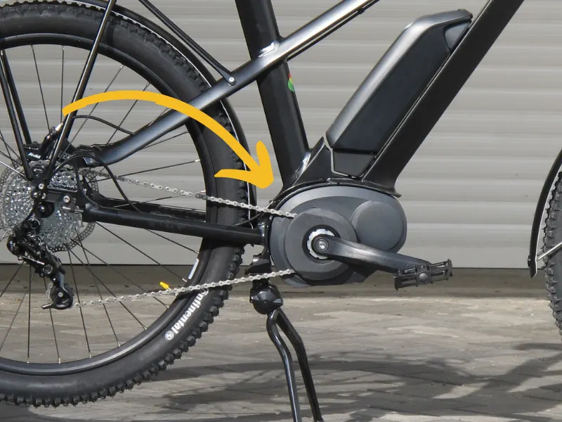
Picture #4 : Mid motor
Mid-drive motors are preferred for hilly, mountainous regions and off-road/trail riding due to better torque and performance on inclines.
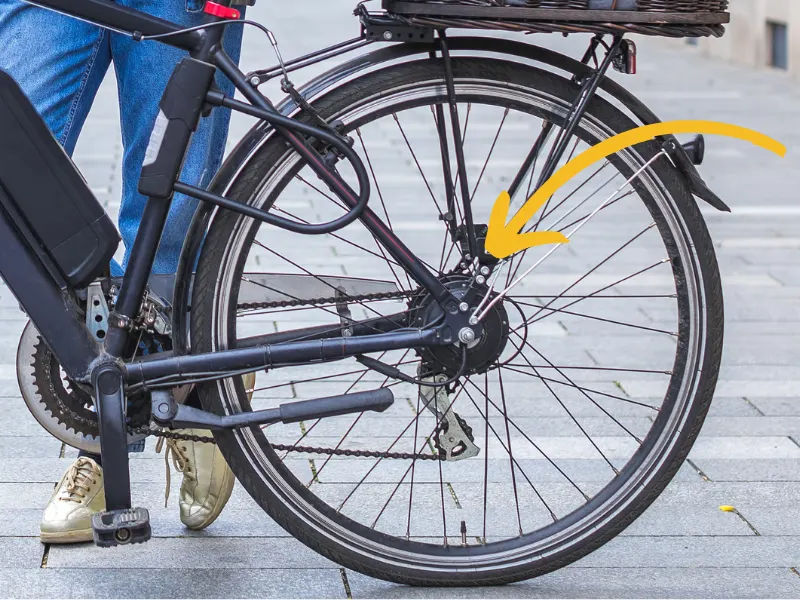
Picture #5: Direct Drive Motor
Direct Drive Motors are best for flat areas and high-speed commutes, known for their durability and smooth ride.
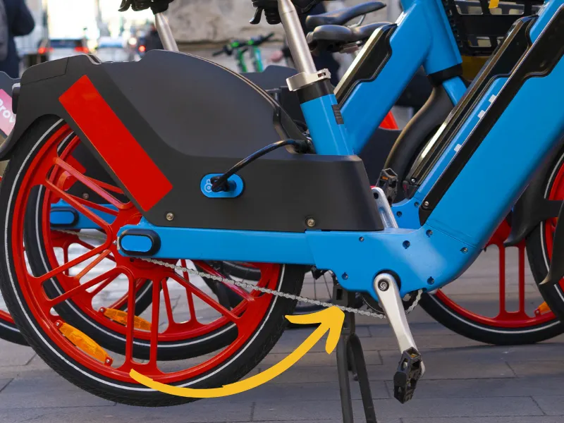
Picture#6 : Geared Hub Motor
Geared Hub Motors are suitable for urban and suburban commuting, providing a balance between power and efficiency for mixed terrains.
How did we design our E-Bike?
We recently transformed a standard mountain bike into a high-performance e-bike by integrating advanced electric components. The upgrade involved installing a rear motor, which significantly enhanced the bike’s power and torque, allowing for smoother and more efficient climbs and descents. Additionally, we incorporated a crankshaft torque sensor that optimizes the bike’s responsiveness by precisely measuring the force applied to the pedals and adjusting motor output accordingly. This ensures a more natural and intuitive riding experience. To further improve control and safety, hydraulic sensors were added, providing reliable and consistent braking performance even under challenging conditions. Together, these upgrades have elevated the bike’s overall performance, making it not only more powerful but also more efficient and responsive. The result is a robust and versatile electric mountain bike capable of handling demanding trails with ease and offering an exhilarating ride for adventure enthusiasts.
Convert a Mountain Bike to Electric Mountain Bike
We chose the mountain bike (MTB) as one of the most attractive bike types for tackling hilly terrains due to its robust design and versatility. MTBs are particularly well-suited for handling the demands of climbing steep inclines and rough trails. One of the key considerations in our design was the incorporation of powerful hydraulic brakes. Given that e-bikes are generally heavier than traditional bikes and can reach higher speeds, having reliable braking power is crucial for both safety and control. Hydraulic brakes offer superior stopping power and better modulation, which is essential for managing the increased weight and speed of an e-bike on challenging terrains.
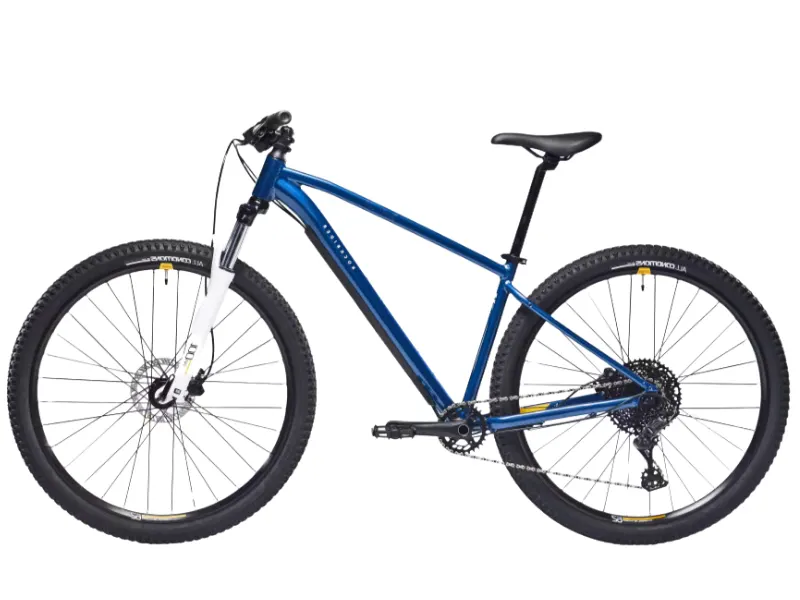
Picture #7: MTB ST-520 by Decathlon
To see more about the bike choice and options follow this link on our youtube video:
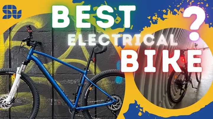
We purchased a mountain bike from the market and upgraded it into an e-bike by installing a rear motor hub. This transformation was done for the normal bike to make it a powerful and efficient electric mountain bike and test our high power controller in the worst cases.
Initially, we aimed to create a full-wheel drive bike with a complex system involving two controllers operating simultaneously. However, we ultimately decided to use the more common configuration of a rear motor hub. After some brainstorming, we outlined the plan as follows:
- Build a rear hub motor wheel
- Acquire a high-power battery with a high-current battery management system and advanced lithium cells
- Install a torque-sensing crankshaft to achieve optimal analog torque response
- Test brake-by-wire technology using a hydraulic brake sensor
In the following sections, we will provide a detailed explanation of each step in detail.
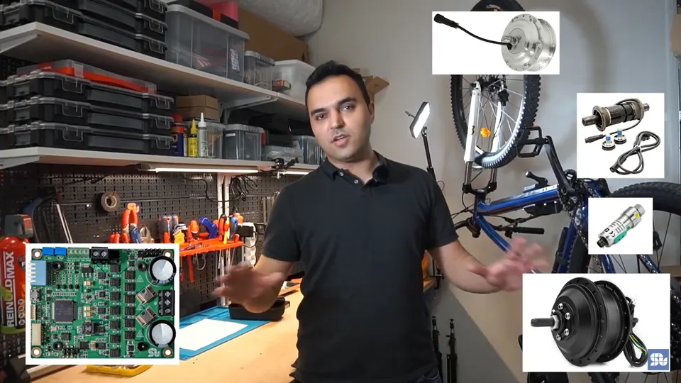
Picture #8: Modules for Conversion of Normal Bike to an E-Bike
In the above pic you can see the modules we thought to use for our project.
First we planned to design a full-wheel-drive e-bike, but we started with a rear-wheel-drive model. Now, we are moving towards creating a full-wheel-drive e-bike. This upgrade will improve traction and stability, giving riders better performance on different terrains.
Torque Sensor Crankshaft for Ebike
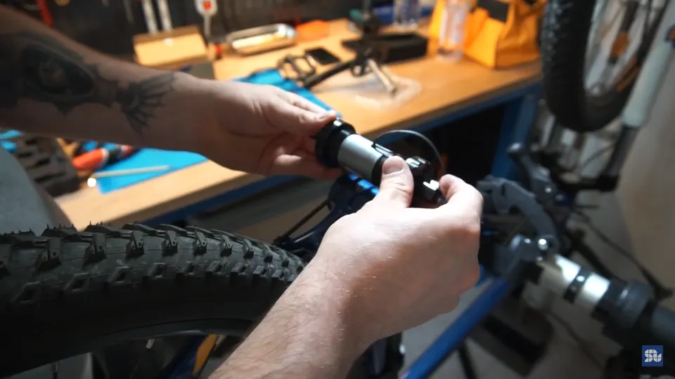
Picture #9: Torque Sensing Crankshaft
As shown in the image above, a torque sensor measures and monitors the torque applied in a rotating system. They are often used in engine, crankshaft, gearbox, transmission, and rotor. In our case the sensor detects the torque that the rider exerts on the shaft of the crank while they are pedaling and it helps the controller to understand how much torque the user wants from the motor to assist . We replaced the original crankshaft with the torque sensing crankshaft.
The amount of recuperation energy can be maintained by the pressure in the hydraulic brake line and used as the feedback for our controller. This method is effective throughout the brake pads’ lifecycle and solely depends on the rider’s input on the brake levers, making it a robust solution for maintaining optimal recuperation energy.
The datasheet and the wiring diagram of the torque sensor crankshaft you find in the illustrations below.
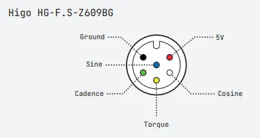
Picture #10: Connection of the Torque Sensor
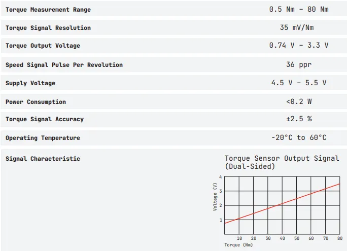
Picture #11: Torque-Voltage Response Range of the Torque Sensor
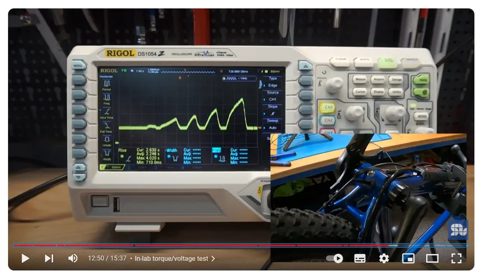
Picture#12:Test Bench Setup and Torque Implementation
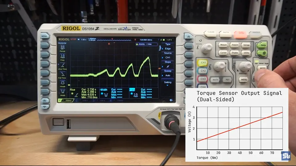
Picture #13 : Peaks of Torque Sensor During the Lab Test
Our setup, as depicted in the image above, consists of a torque sensor connected to an oscilloscope through the following connections: sine, cosine, voltage, cadence, and ground. We calibrated the oscilloscope and set the reference voltage to 0.8V. Then, we applied torque manually, gradually increasing the amount. The initial torque value recorded was 1.3V, corresponding to approximately 10 Nm on the plot. The next value was 1.4V, roughly equivalent to 20 Nm. The third value was 1.7 V, equating to about 30 Nm, and the final reading was 2.35V, exceeding 40 Nm.
Below you can find the Youtube Video for our Lab Test:
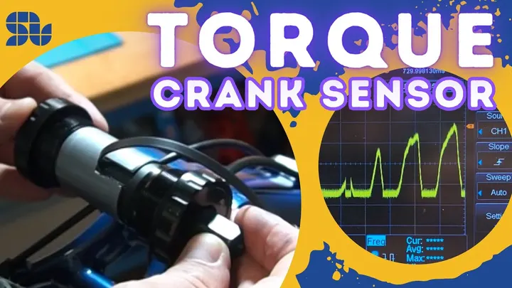
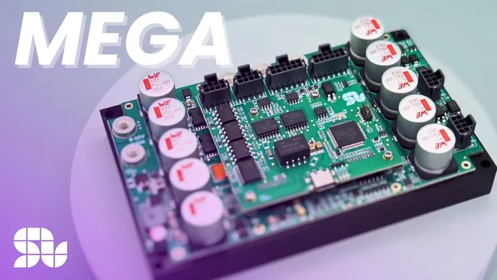
The controller is supposed to be powered by a 48V battery, in our lab we used the power supply with the same performance to control the current, voltage and have short circuit and polarity protection. The rear motor hub connects to the controller via three motor connections labeled A, B, and C. Additionally, the motor provides feedback to the controller through hall sensors. The torque sensor is linked to the controller with three connections: 5V, TORQUE, and GND, offering torque feedback. The torque sensor analog output (TORQUE) served as the reference for determining the level of motor assistance, with 0V indicating no assistance and 3.3V indicating maximum assistance. The S/T analog input of the controller operates within a 0 to 12V range. To enhance performance, we updated our controller firmware to increase the voltage from 3.3V to 12V. In the test trials shown in the video, we utilized our SOLO UNO controller. However, for the final setup, we opted for the SOLO MEGA controller, the most powerful one available in our lab.In addition, the STO (Safe Torque Off) was utilized for safety reasons.
You can have a look at our most powerful controller SOLO MEGA in the video below :
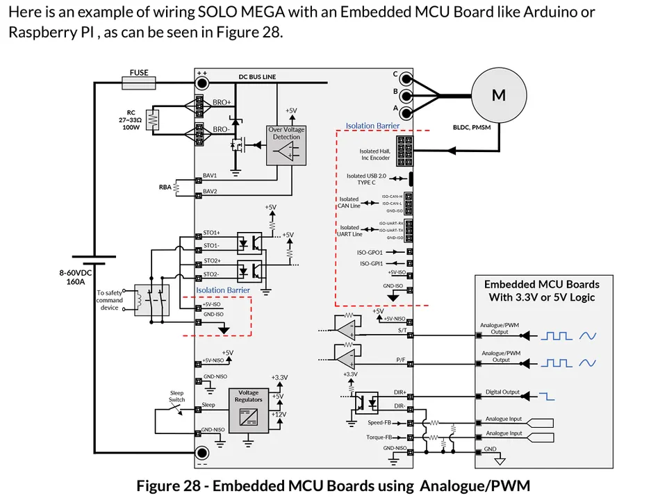
Picture #14: Wiring Connection of SOLO MEGA (PAGE 66)
Motor Rear Hub for EBike
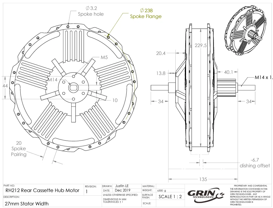
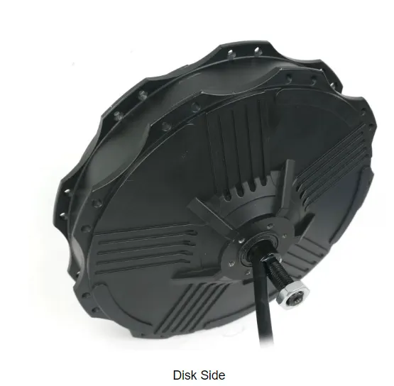
Picture #15 : Motor Hub Drawings and Wiring Diagram
The most fundamental block of the bike which converts it to e-bike is the electrical motor . This is a 1kW 80 nm motor and is to be used as a rear wheel motor. We bought the motor hub kit from the Grin Lab and we assembled the motor hub as shown. We used the high speed version of it. We put it on the bike and tested it with a controller. We couple the controller with the torque sensor on the crankshaft and see how they work together in the analogue manner.
Rear motor hubs include improved traction, a more natural riding feel, and better weight distribution. However, they can be heavier and more challenging to service than mid-drive motors. Despite these drawbacks, the robust design and enhanced performance make rear motor hubs a popular choice for e-bikes.
We used the embedded hall sensor connection in the rear motor hub to enhance the performance and reliability of electric. Its accuracy in measuring speed and position, coupled with its robustness, makes it an ideal choice for such applications. This ensures a smoother, safer, and more efficient riding experience.
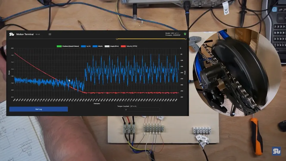
Picture #16: Performance Analysis of Motor During the Lab Test
We conducted a performance and analysis test on the motor by applying 36V and 6A. The motor has 46 poles. Using a motion terminal, we configured the necessary values. The test was performed in speed mode, and the torque mode, as demonstrated in the video and results. For more detailed overview please watch our youtube video over here:
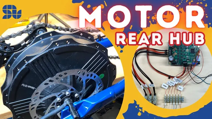
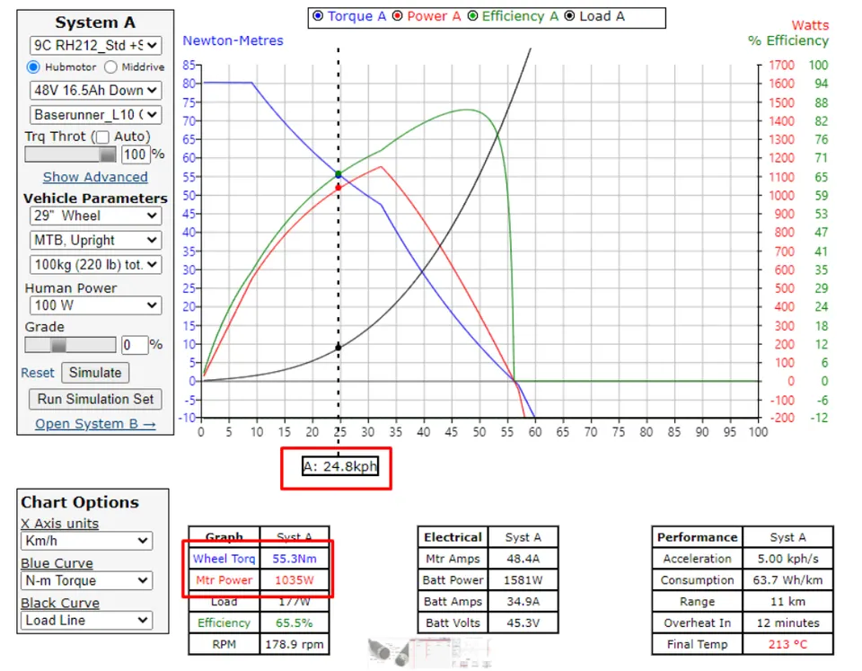
Picture #17: Curves of the Motor During the Lab Test
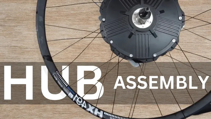
During our lab session on wheel assembly, we faced an issue with rim selection because the number of spoke holes in the rim did not match those in the motor hub, and they needed to be identical. Despite this, we assembled the spokes and attached the motor to the rear wheel. The motor was connected to a power supply, and we linked a Hall sensor to the controller, activating the performance monitor. Additionally, we connected a torque crankshaft to test how the torque produced by the crankshaft influences the motor hub. This was tested under both assisted and unassisted conditions, and various results were observed.
More about the test setup in the Youtube video below:
Hydraulic Brake Sensor and Brake by Wire
Picture #18: Hydraulic Brake Sensor
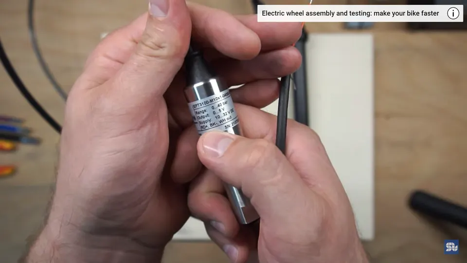
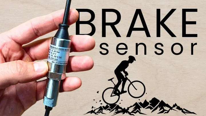
A hydraulic brake sensor is a device designed to detect changes in hydraulic pressure within the brake system and convert this physical change into an electronic signal. This signal can then be used to interact with other systems, such as the E-Bike motor controller as recuperation energy reference. In this design, we aimed to implement a brake-by-wire system, where the brake lever on the bike’s handlebar operates without any direct connection to the brake caliper and pads.
The parameters of the pressure sensor we used are :
Range:0-40 bar
Output:0-5V
Supply:10-32V DC
The datasheet and wiring diagram of this hydraulic sensor depicted in the image below.
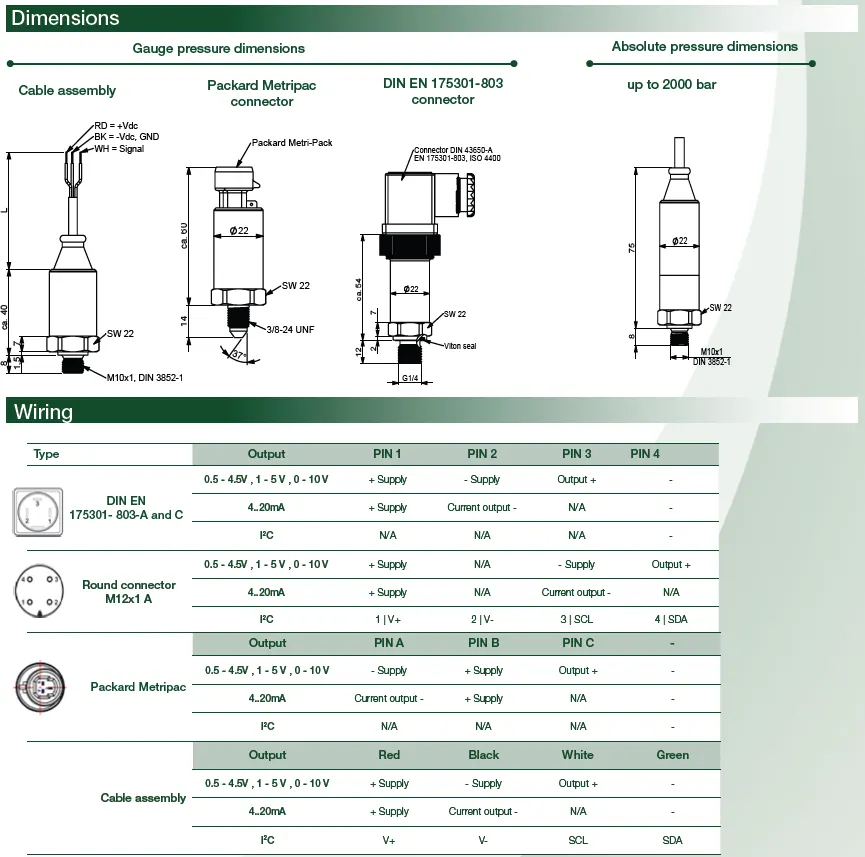
Picture #19: Datasheet of the Torque Sensor
Usually the amount of recuperation energy in e-bikes is controlled by a position sensor mounted on the brake lever, but this method is not accurate and does not provide the rider with a proper brake feel. That’s why we replaced it with the hydraulic brake sensor to get the analog feedback signal and give the rider more real experience.
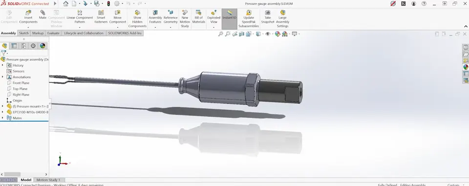
Picture #20: Transducer Sleeve for Connection of Pressure Sensor and the Tube (3D model)
To connect the Pressure Sensor and the tube we created the Transducer Sleeve as you can see in the image above.
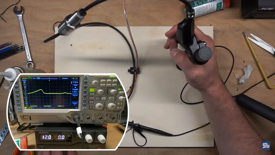
Picture #21: Hydraulic Brake Output During the Test
To test the Hydraulic Sensor, we connected it to the hydraulic brake and a Power Supply, setting the reference to 12V and 1A. As we applied the brake, pulses appeared on the oscilloscope, with higher pressure resulting in more voltage pulses. This input reference will be used to control recuperation in our controller. Since we have another Analog Input P/F on our controller, we can manage this control effectively. The sensor’s maximum limit is 5V/40 bar, but we don’t need the full range as we use full brakes beyond a certain point. We implemented this system on our E-Bike. We believe that mounting the pressure sensor closer to the caliper will reduce the hydraulic delay and improve system response time.
For more details watch the Youtube Video below:
Ebike Battery and Controller Mount
To power up the entire system it is needed a High Current battery with the Advanced Lithium Cells. We found a custom triangle-shaped battery for e-bikes with the following specifications:
- Voltage: 48V DC
- Capacity: 30Ah
- Cell Type: Samsung 50E lithium cells
- Battery Management System (BMS): Supports up to 70A
- Charger: 4A
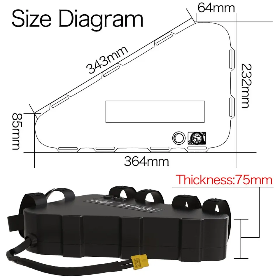
Picture#22: Battery Specification
Battery Mount
To secure the battery from the e-bike frame and prevent cell damage from high-frequency vibrations, we designed and 3D printed custom dampers. The battery and dampers are shown in the accompanying figure.
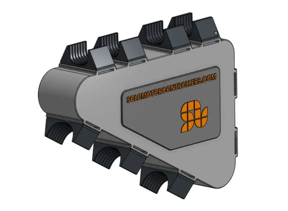
Picture #23: Battery Mounts
SOLO MEGA Mount
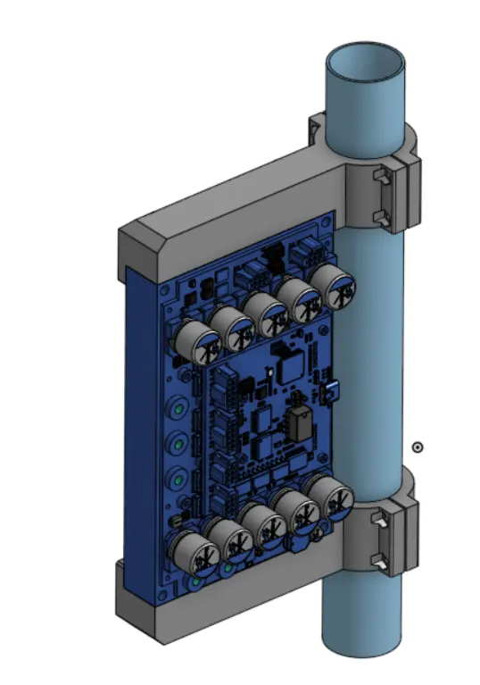
Picture #24: SOLO MEGA EBIKE Mounts
For this Ebike we choose an aggressive and powerful motor controller, SOLO MEGA. The mounts are designed to attach to the vertical tube of the bike frame. These mounts are 3D printed with ABS filament, as the heatsink might reach temperatures up to 100°C. The 3D models are shown in the figures above.
The First Riding Experience
Our lab-built E-Bike now features a torque sensor linked to the controller to regulate motor assistance. The battery, secured on custom dampers, supplies power. The SOLO Mega controller, which is a powerful controller, is mounted on the frame and manages power conversion from the battery as well as feedback signals to control the motor’s current. The rear motor hub drives the powertrain, while a hydraulic brake sensor provides data for energy recuperation. Additionally, there is a complex network of wires connecting all these components.
The schematics of it illustrated below:
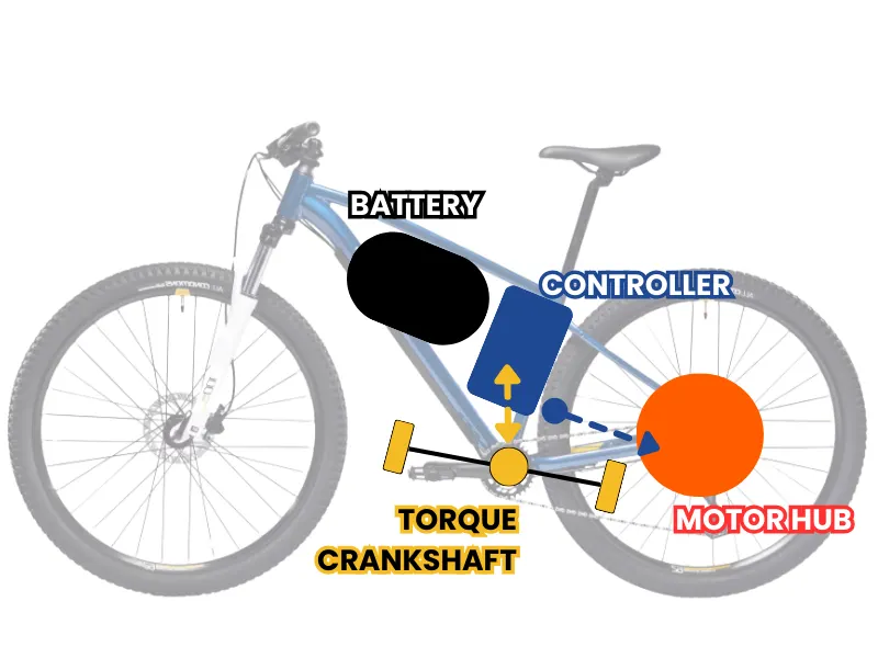
Picture #25 : E-Bike with schematics
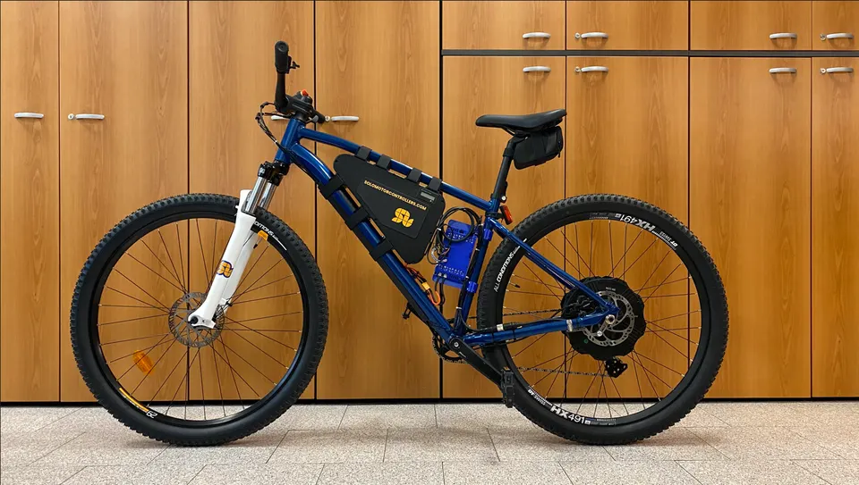
Picture #26: E-Bike We Developed
Conclusion
Converting a traditional bicycle into an electric bike with our motor controller has been a rewarding use case demonstration, giving the possibility to show new angle to possible innovation and how flexible products can be used differently.
We will continue to experiment and testing to further improve e-bike performance, efficiency, and versatility. We will continue to conduct new experiments and tests to optimize the bike’s capabilities as the capability of our motor cotrollers. This ongoing development will enable us to explore new engineering solutions and integrate emerging technologies.
As believer in this technologies, we encourage collaboration with fellow engineers and companies to advance the field of e-bike
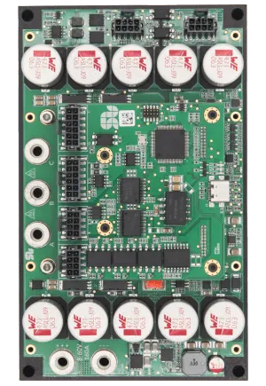
Products in this article
Related articles
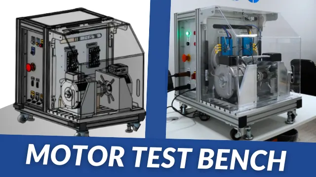
Portable Electric Motor Test Bench
A test bench is an assembly or system designed to test the functionality and performance of a motor or motor controller under various conditions. It simulates
Exploring Degrees of Freedom (DOF) in Motion Simulators
This article explores key concepts like Degrees of Freedom (DOF) and their applications, highlighting implementation, advantages, and limitations.
Sensorless Control of Brushless or Permanent Magnet Synchronous Motors in Wide Speed Range
Sensorless control eliminates the need for shaft sensors, reducing cost and improving reliability, here a description of possibility given with this tech
