
Portable Electric Motor Test Bench
What is a Test Bench?
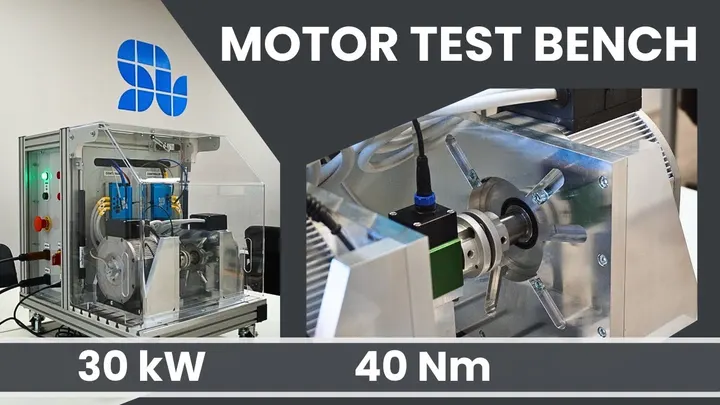
A test bench is an assembly or system designed to test the functionality and performance of a motor or motor controller under various conditions. It simulates real-world operating scenarios to ensure that the motor controllers perform as expected, without needing to install them in a live, operational setup. Test benches help detect and resolve potential issues such as overheating, inefficiencies, and faults early in the development process.
A test bench is an integrated setup designed to evaluate motor controllers and motors under various conditions. Composed of core components like a desktop computer, controller, motor, feedback systems, and sensors, the test bench simulates real-world operating environments to measure performance, durability, and efficiency. Test benches provide a controlled environment where motor controllers can be stressed under specific conditions to detect issues before deployment.
Types of Test Benches
Test benches can vary widely in design and function depending on the application. Here’s a breakdown of some common types of test benches for motor controllers:
| Type of Test Bench | Electrical Test Bench | Mechanical Test Bench | Environmental Test Bench | Dynamic Load Test Bench | Endurance Test Bench |
|---|---|---|---|---|---|
| Description | Simulates electrical parameters like voltage, current, and power. | Tests the physical performance of motors under simulated loads. | Simulates extreme environmental conditions, such as temperature and humidity. | Uses simulated dynamic loads that change based on speed, torque, or other variables. | Runs continuous tests to evaluate long-term durability and performance. |
| Applications | Evaluates the motor controller’s electrical response to different scenarios, such as voltage drops or overloads. | Used for examining torque, vibration, and speed characteristics in motor controllers. | Ensures reliability of motor controllers in adverse conditions, common for automotive and aerospace applications. | Assesses the controller’s ability to handle changing loads, crucial in applications like robotics and manufacturing. | Ideal for applications requiring high reliability, such as electric vehicles and heavy-duty machinery. |
Sizes of Test Benches: Small, Medium, Large, and Mega-Scale
Not all test benches are the same size. The size of a test bench often depends on the type of motors and controllers it is designed to test, as well as the complexity of the testing parameters. Here’s a breakdown of the different sizes and their typical uses:
| Test Bench Size | Small | Medium | Large | Mega-Scale |
|---|---|---|---|---|
| Description | Compact and often portable. Usually sits on a desktop with limited testing capabilities. | Larger than small benches, with added capabilities for a wider range of motor controllers. | Full-sized setup with extensive control and monitoring, often occupying a dedicated room. | Enormous systems that span multiple floors in a building, sometimes dedicated entire rooms or stories. |
| Typical Use Cases | Ideal for lab research, educational settings, and small motor testing. | Common in R&D departments, capable of handling medium-sized motors and controllers. | Used in industrial settings for high-performance motor testing. | Essential for testing very high-power motors, such as those used in aerospace or heavy machinery. |
Mega-scale test benches are unique in their scope, often testing massive motor systems like those used in aerospace, power generation, and large-scale manufacturing. These test benches are complex setups, often requiring custom-built rooms with reinforced structures to support heavy machinery and prevent vibration interference.
Components of a Test Bench
While test benches vary in size, they share core components that make accurate testing possible:
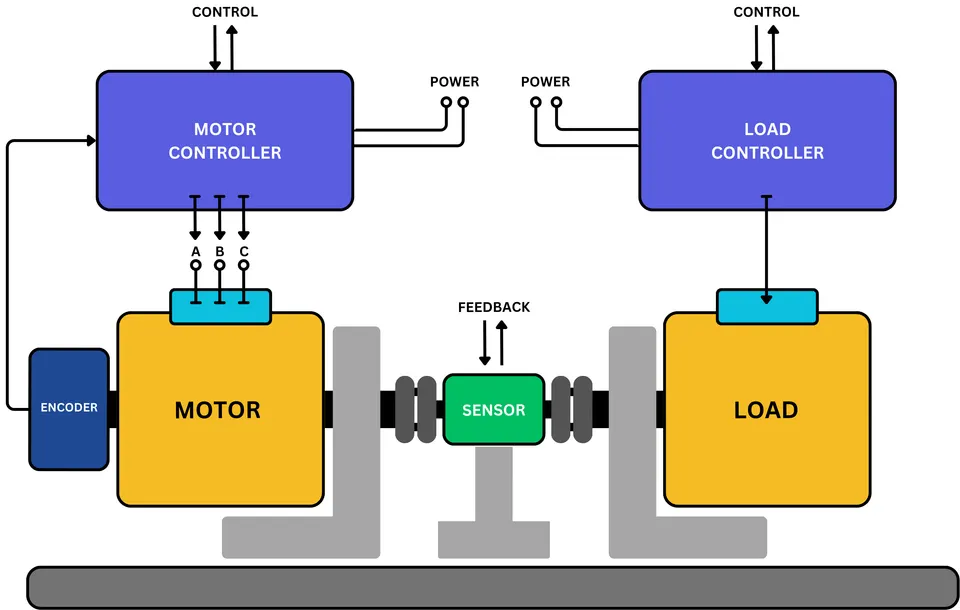
- Desktop/Control System: Serves as the primary user interface for operating the test bench, logging data, and analyzing results, usually it’s a laptop.
- Motor/Load Controller: The core of the test bench, responsible for directing and managing testing parameters such as voltage, torque, and speed.
- Motor: The unit under test, connected to the controller to simulate real-world operating scenarios.
- Load: Can be any type of load, such as a mechanical or powder brake, or even an electrical motor, which generates torque to challenge the tested motor.
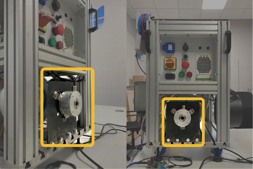
- Motor Feedback System: Typically an encoder, ensures precise measurements of motor performance by providing data on speed, position, and response time.
- Sensors: Monitor variables like temperature, torque, vibration, and current to deliver a comprehensive understanding of motor behavior.
- Mounting Plate: A reliable rigid base that securely holds the motors in place, preventing movement or displacement during testing.
Each component plays a critical role in ensuring that a test bench provides precise and useful data. Larger test benches often include additional components, such as reinforced frames and advanced cooling systems, to handle the stress of heavy-duty testing.
Types of Tests Performed on Motor Controller Test Benches
Test benches are essential for verifying motor controller performance across various conditions. Here’s a quick look at the most common test types performed on different test bench setups.
1. Controller Tests
These tests assess how well the motor controller regulates speed, voltage, and current, and include:
- Response Time: Measures how quickly the controller reacts to input changes.
- Fault Tolerance: Simulates faults and overloads to test the controller’s resilience and recovery.
- Control Approaches: Includes field weakening for achieving higher speeds and sensorless control methods.
- Firmware Behavior: Evaluates the performance of both standard and custom firmware.
- Motor Control Dynamics: Assesses how quickly the motor transitions between operational conditions.
- Efficiency and Power Consumption Analysis: Analyzes the energy required to operate the motor under various conditions
2. Motor Tests
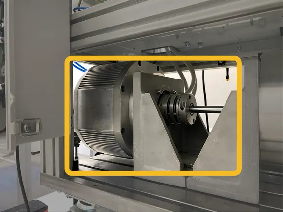
Motor tests verify torque, speed, and efficiency, and include:
- Torque and Speed: Evaluates the motor’s performance under load conditions, including its response and stability.
- Vibration and Efficiency: Measures the motor’s operational stability and energy consumption.
- Control Approaches: Tests various control techniques tailored for different motor types.
- Motor Dynamic Test: Assesses mechanical speed, acceleration, and deceleration in no-load conditions.
- Mount Test: Examines the ease of motor mounting and wiring connections.
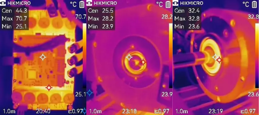
3. Temperature Tests
Temperature tests evaluate performance in extreme heat or cold:
- Thermal Overload: Assesses the motor’s and controller’s heat dissipation capabilities during high-load operation to prevent overheating.
- Cold Start: Evaluates the motor’s performance and responsiveness at low temperatures.
- Enclosure Behavior at Higher Temperatures: Examines how the motor enclosure handles elevated temperatures, ensuring durability and safety.
- Heatsink and Thermal Pad Efficiency: Tests the effectiveness of heatsinks and thermal pads in dissipating heat and maintaining optimal operating conditions.
4. Sensor Tests
Sensors are crucial for accurate measurements; these tests ensure sensor reliability:
- Accuracy and Latency: Evaluates sensor precision and response time to ensure reliable data acquisition.
- Environmental Tolerance: Tests the performance of sensors under challenging conditions such as humidity, dust, and vibration.
- Mechanical Behavior: Assesses sensor performance during high-speed operations and exposure to vibrations.
- Robustness: Ensures feedback stability across various operating conditions, including temperature and load variations.
5. Load Tests
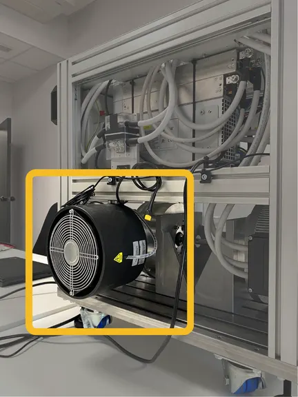
Load tests assess motor-controller stability under different loads:
- Static and Dynamic Load: Assesses performance under steady-state and varying load conditions.
- Overload: Evaluates the system’s response to loads exceeding its rated capacity.
- High Load Start: Tests current surge and overcurrent handling during high-load startups.
- Mechanical Performance: Analyzes the consistency of load levels during high-speed operations and under vibration stress.
6. Endurance Tests
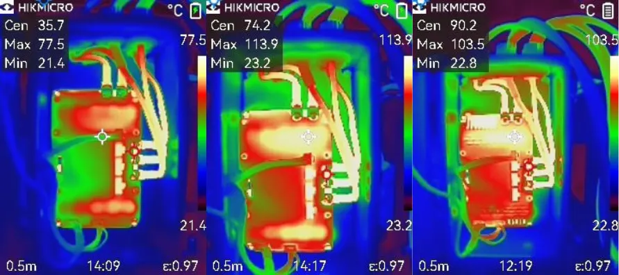
These tests measure long-term durability:
- Continuous Operation: Simulates prolonged operation to evaluate performance and durability under extended use.
- High-Duty Cycle: Tests the system’s reliability during repeated startups and shutdowns over time.
- Resilience: Assesses how the motor and controller handle high-load conditions in steady-state operation over extended periods.
- Peripheral Elements Robustness: Evaluates the durability of connectors, enclosures, and wiring under long-term high-performance operation.
30kW Mobile Desktop Motor Test Bench
In our laboratory, we primarily work with low-to-mid power motors that are compatible with SOLO Motor Controllers and can be tested against their datasheets. Our previously designed test bench allowed us to perform various types of tests, including endurance, load, and temperature tests. It was also instrumental in achieving multiple certifications for our controllers.
This motor test bench was redesigned for one of our customers to meet their specific requirements for testing new types of controllers. Some of their critical demands included an external DC power supply (as they already had one), a universal mount for different motor types, reliable power control capable of handling up to 200A, safety features, CAN and USB ports on one of the control panels, compact size and weight, and mobility.
In this chapter we’ll explain the design and control features which helped us to achieve the requirements. If you’re interested in our previous motor test bench please follow this link and subscribe to our channel.

Aluminum Beams
The aluminum beams are used as the primary structural elements for assembling the core frame. This frame can then be complemented with bent panels, standard mounts such as handles and hinges, wheels, stands, and other accessories.
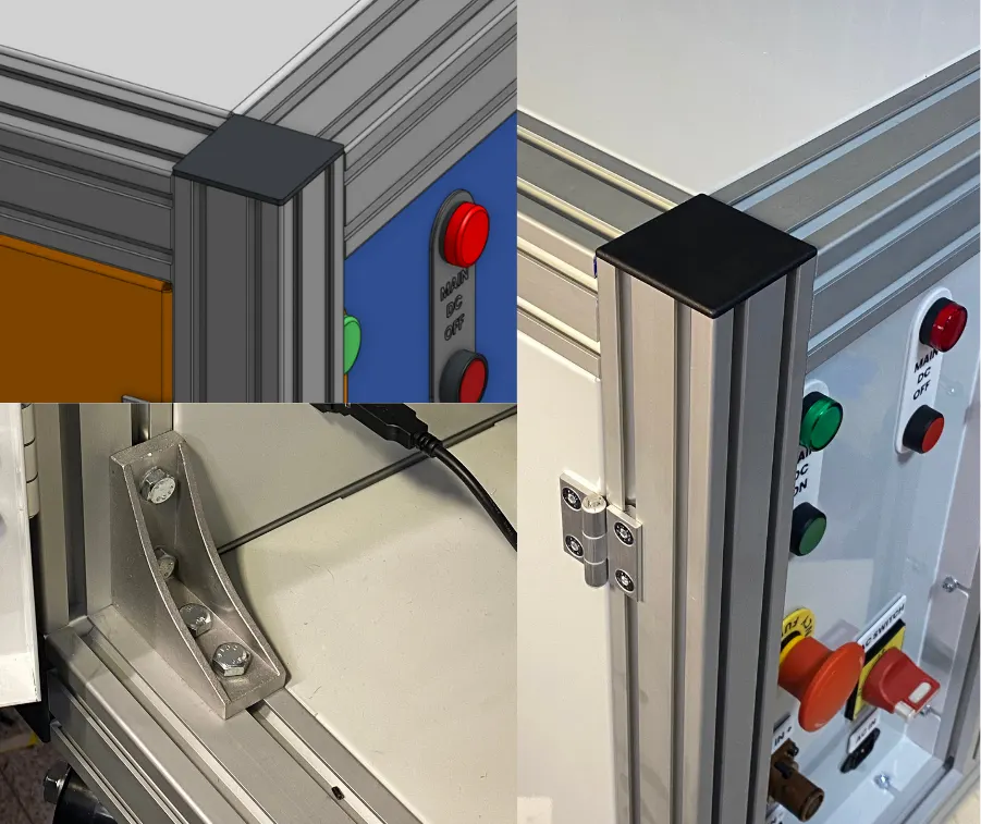
- Description: The frame of the test bench is constructed from aluminum beams.
- Benefits: Aluminum beams are lightweight, rigid, and durable, providing structural support without adding excessive weight. They also feature a universal light mount, making it easy to attach various components, instruments, and equipment.
- Ease of Use: The modular design of aluminum beams simplifies setup, adjustments, and mounting, allowing for versatile configurations depending on test requirements.
T-Slot Plate
High-stiffness industrial T-slot plates are commonly used in CNC machines to secure machined parts. Their widespread use has resulted in the availability of numerous fixturing devices, nuts, and bolts, and their exceptional accuracy and flatness make them highly reliable. These qualities are also advantageous in other applications, such as standardizing motor and sensor mounts. The T-slot plate provides a dependable surface that ensures axial alignment and robust mounting solutions.
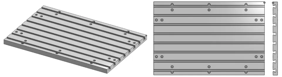
- Description: This is a standard CNC-type mount plate with T-slots, allowing for flexible and secure placement of various components.
- Functionality: The T-slot plate enables precise positioning of motors, sensors, loads, and other test equipment. This standard design ensures compatibility with a range of motor sizes and test setups, promoting flexibility and ease of reconfiguration.
- Advantages: The T-slot design offers easy assembly and repositioning, making it ideal for iterative testing processes.
Progressive Design of Motor Brackets
One of the most critical and frequently used components is the motor/load bracket. Our experience shows that the more universal the bracket, the quicker the tests can be conducted, minimizing the need for additional machining and reducing time and cost inefficiencies. However, this approach has its limitations, as some motors have completely different mounts such as outrunners or mounting hole positions that deviate significantly from standard universal brackets.
Our solution accommodates motors with three- or four-bolt types mounting configurations, where the mounting holes are equidistantly positioned along a curve with a minimum diameter of 120 mm and a maximum of 210 mm. These brackets are compatible with M8 bolts or thinner bolts when used with additional washers.
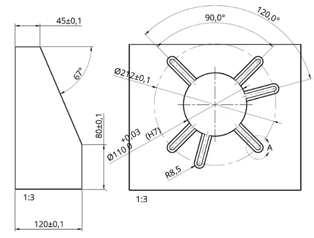
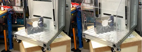
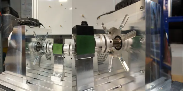
- Description: The motor brackets are designed with a progressive layout that allows for versatile mounting and support.
- Pros/Cons Analysis: The brackets have been optimized to address the needs of various testing setups. The strengths of this composition, such as increased stability, vibration control, and compatibility with different motor sizes. However, this design might be bulkier compared to simpler bracket designs.
- Industrial Relevance: The design features mortises compatible with both 3-hole and 4-hole mount type motors. This flexibility allows different types of motors to be used with the same design brackets, enhancing the economic efficiency of the test bench.
Industrial Wheels, Damped Stands, and Handles
The industrial approach used in designing the motor test bench ensured it is both robust and safe. However, the assembly is relatively heavy, requiring proper wheels to make it mobile and easy to transport. Additionally, damped stands are essential to ensure a stable and level horizontal platform for conducting tests.
This design incorporates a combined solution of wheels and stands, simplifying the construction and saving space while maintaining functionality and stability.
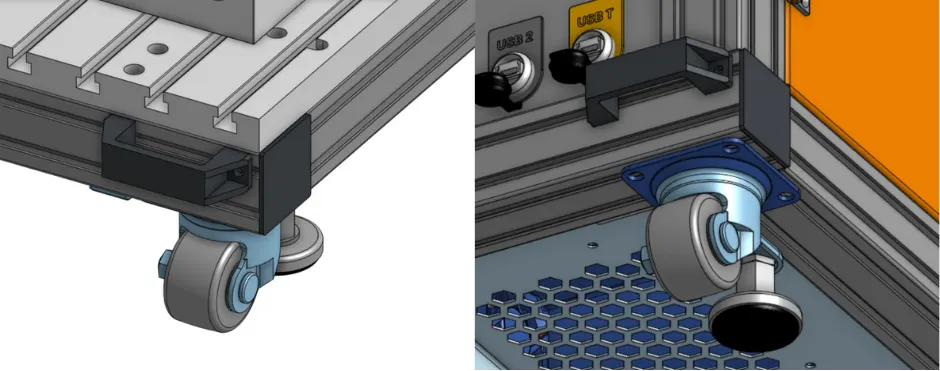
- Description: The test bench is equipped with industrial-grade wheels and damped stands.
- Handles: Placed in each corner of the machine to make any movements easier and safer
- Mobility: The wheels make it easy to move the test bench to different locations within a facility. Once in place, the wheels can be locked to secure the bench during testing.
- Vibration Control: The damped stands absorb vibrations, minimizing interference during tests and providing a stable testing environment.
Closed Chamber (Safety + Temperature insulation)
Testing motors or loads often carries risks of mechanical failures, increasing the likelihood of hazards. The powertrain includes components such as shafts, couplings, sensors, and other devices with wires and mounts, which, if improperly secured, can be ejected from the operating area. To address this, a safety cover made of 5mm plexiglass was designed.
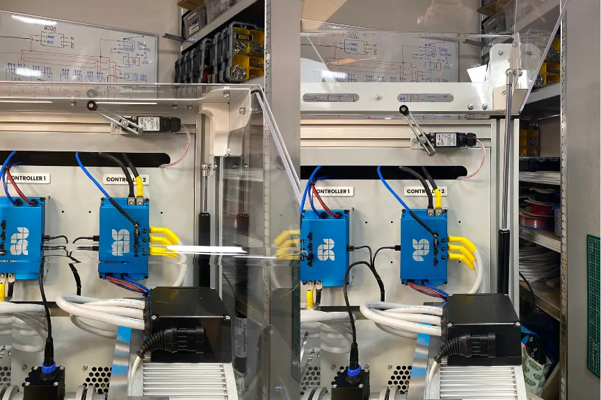
The cover is mounted on two industrial hinges attached to aluminum beams using standard mounts. Additionally, air springs are installed on both the right and left sides of the cover to keep it securely closed or assist during opening. A safety limit switch detects when the cover is slightly opened and activates the Safe Torque Off function to ensure operational safety (page 49 of SOLO MEGA User Manual).
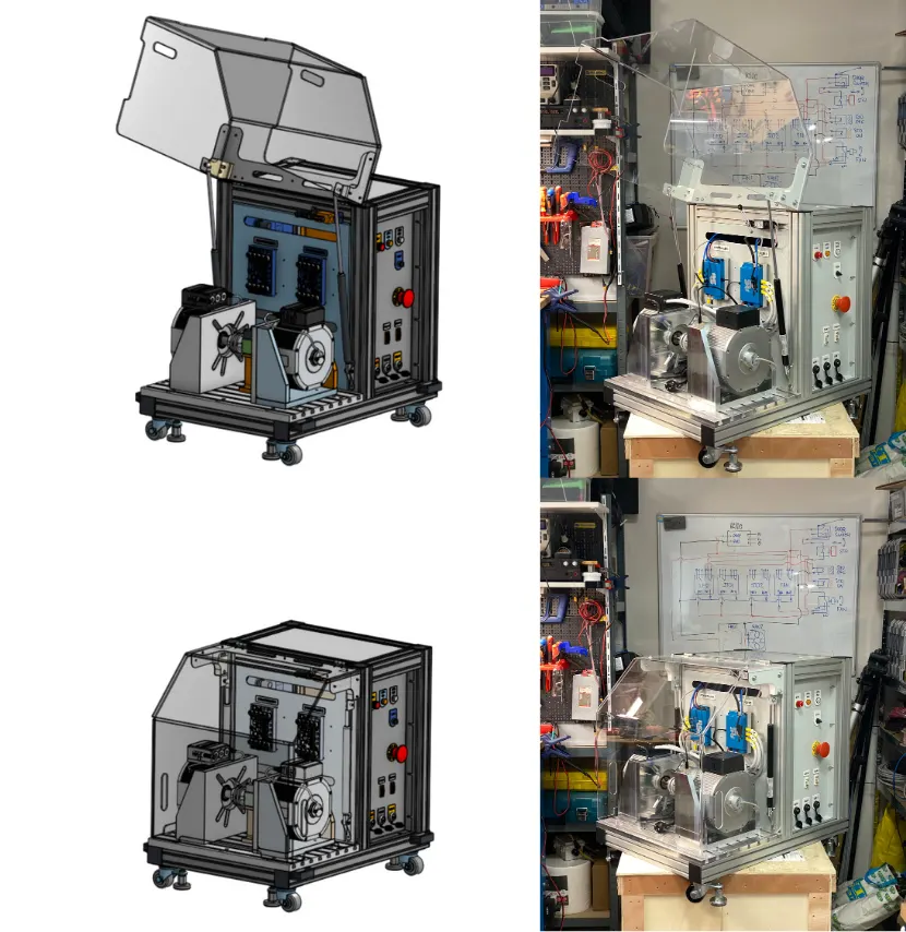
- Description: The test bench includes a closed chamber designed for controlled testing conditions.
- Purpose: This chamber was primarily designed as a safety cover feature but also enables temperature testing, allowing engineers to monitor how the motor and controller respond to different thermal conditions. It provides a layer of safety by containing any potential hazards that may arise from motor overheating or failure.
- Benefits: A closed chamber improves the accuracy of environmental tests and ensures safer testing in high-stress scenarios.
Additional Exhaust in the Chamber to Avoid Overheating
In a closed chamber, it is crucial to consider that motors and controllers generate significant heat during high-power operation. To prevent overheating, additional notches and gaps were incorporated into the design to enhance ventilation, and two extra exhaust fans were installed to ensure proper air circulation. These fans are powered by 24VDC and are controlled via an additional switch and relay for efficient operation.
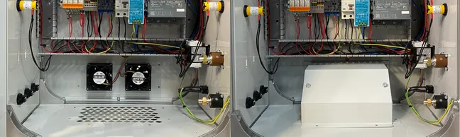
The exhaust ventilation system is created using an additional bent component. The airflow enters through the front cover cuts, passes through the operating area’s back panel, and expels warm air through a grid located in the bottom panel of the electrical cabinet, as illustrated in the figure below.
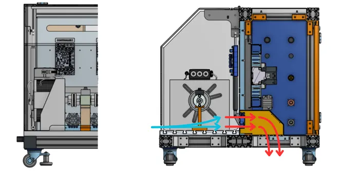
- Description: An additional exhaust system is installed in the closed chamber.
- Function: This exhaust helps maintain a stable temperature by removing excess heat, ensuring the motor and controller do not overheat during prolonged tests.
- Importance: Proper ventilation is crucial for preventing component damage and maintaining consistent test results over extended periods.
Closed Electrical Cabinet
The second crucial component, after the operating area with high-power mechanical devices, is the electrical cabinet. A reliable contactor is required to handle the 200A current, controlled by other relays and buttons located on the operator panel. All electrical components must be housed in a closed, secure space where they can be safely wired and easily maintained if necessary.
In this case, an industrial approach helped create a simple electrical panel, which was later installed in the machine and wired in place, as shown in the following images.
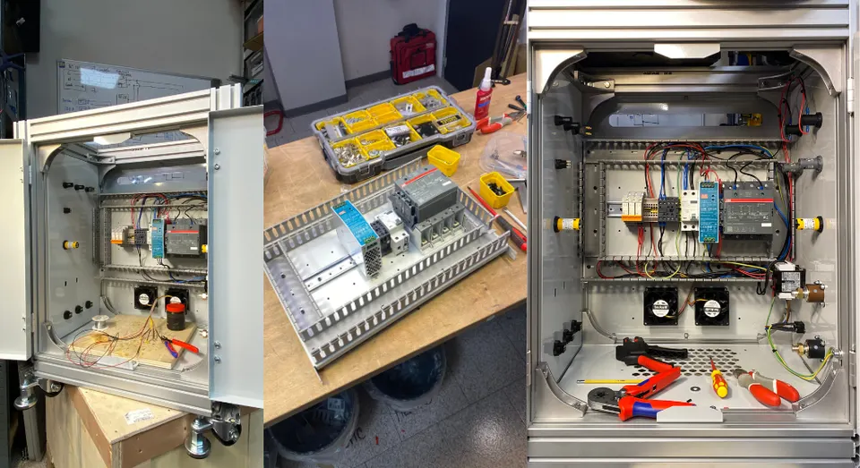
_**Figure 17. Electrical panel with some components in the middle and installed in the machine (L) and (R).
**_
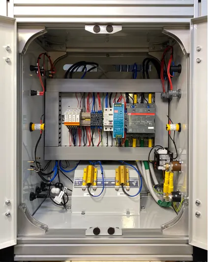
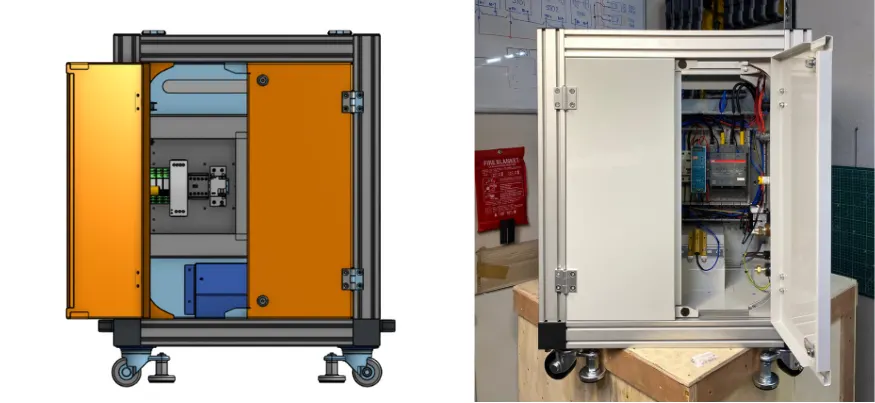
_**Figure 19. Electrical cabinet back doors in 3D model (L) and real machine (R).
**_
- Description: A dedicated closed electrical cabinet houses the test bench’s electrical components.
- Function: The closed cabinet protects sensitive electrical systems from environmental factors, such as dust, moisture, and accidental contact.
- Safety and Organization: By isolating electrical components, the cabinet ensures a safer workspace and organizes cables, power supplies, and controllers neatly.
In/Out Control Panels
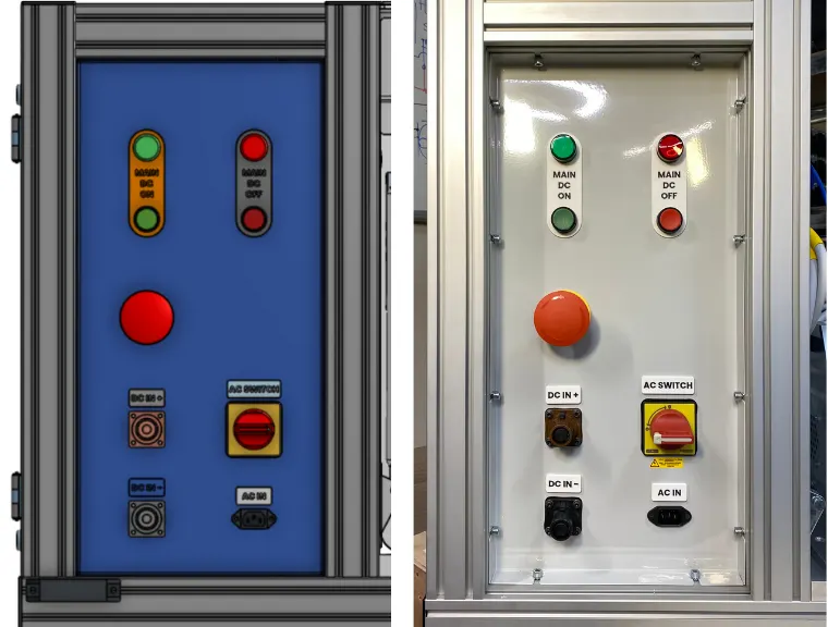
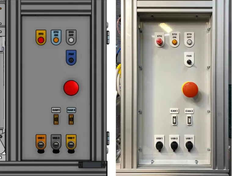
The motor test bench is designed with operator convenience in mind. This requires control panels to be organized in a clear, minimalist layout, with signs and labels that are readable and self-explanatory. Reliable control buttons and safety switches further enhance usability and safety.
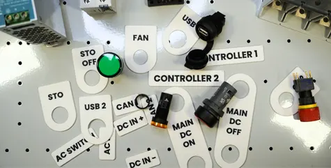
_**Figure 20. Panel control elements and labels.
**_
The panels are divided into two main sections:
- Power Input Control Panel: Includes the main power controls, AC and DC inlet sockets, and a safety quick-release button.
- Data Output Control Panel: Features STO control and status lights, as well as controls for the fan, USB ports, and CAN connectors.
For more details, please refer to the images below.
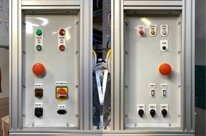
- Description: The test bench includes control panels that can be positioned internally or externally.
- Flexibility: These panels allow for seamless operation and monitoring of the test bench, offering options for direct control or remote operation.
- Ease of Use: With accessible control panels, users can easily adjust test parameters and monitor performance in real time, improving workflow and efficiency.
Components
As the main components in this motor test bench are listed below
Drive and Load Sides
For both Drive and load sides high end 3-Phase IPM Synchronous Electric Motors were used.
IPM Synchronous Electric Motors (Interior Permanent Magnet Synchronous Motors) are widely used across various industries and applications due to their high efficiency, compact size, and superior torque characteristics. Here’s a brief overview of their common applications:
- Automotive Industry:
- Electric and Hybrid Vehicles: IPM motors are extensively used in electric and hybrid vehicles for propulsion systems. Their high torque-to-weight ratio and efficiency make them ideal for automotive applications.
- Auxiliary Systems: They power components like electric power steering, HVAC systems, and pumps.
- Industrial Automation:
- Robotics: IPM motors are used in robotics for precise motion control and energy-efficient operation
- CNC Machines and Manufacturing: Their ability to maintain consistent torque at various speeds makes them suitable for precision machining and automated production lines.
3. Renewable Energy:
- Wind Turbines: IPM motors are used in wind turbine generators due to their efficiency and reliability.
- Solar Tracking Systems: Their precision control helps optimize the positioning of solar panels.
4. Home Appliances:
- High-Efficiency Appliances: IPM motors are found in washing machines, refrigerators, and air conditioners, where energy savings and performance are prioritized.
5. Aerospace and Defense:
- Used in advanced systems like unmanned aerial vehicles (UAVs), actuators, and auxiliary power units where high power density and reliability are critical.
- Energy Storage and Distribution:
- Electric Grids: They are used in grid energy storage systems and for managing power distribution.
Advantages Driving Their Use:
- High Efficiency: IPM motors maintain high efficiency even under varying load conditions.
- Compact Design: Their interior magnet configuration allows for a smaller, lightweight design.
- Robust Performance: They offer excellent torque at both low and high speeds, making them versatile for various applications.
IPM motors continue to gain traction in industries that prioritize efficiency, performance, and sustainability. Let me know if you need detailed insights into any specific application!
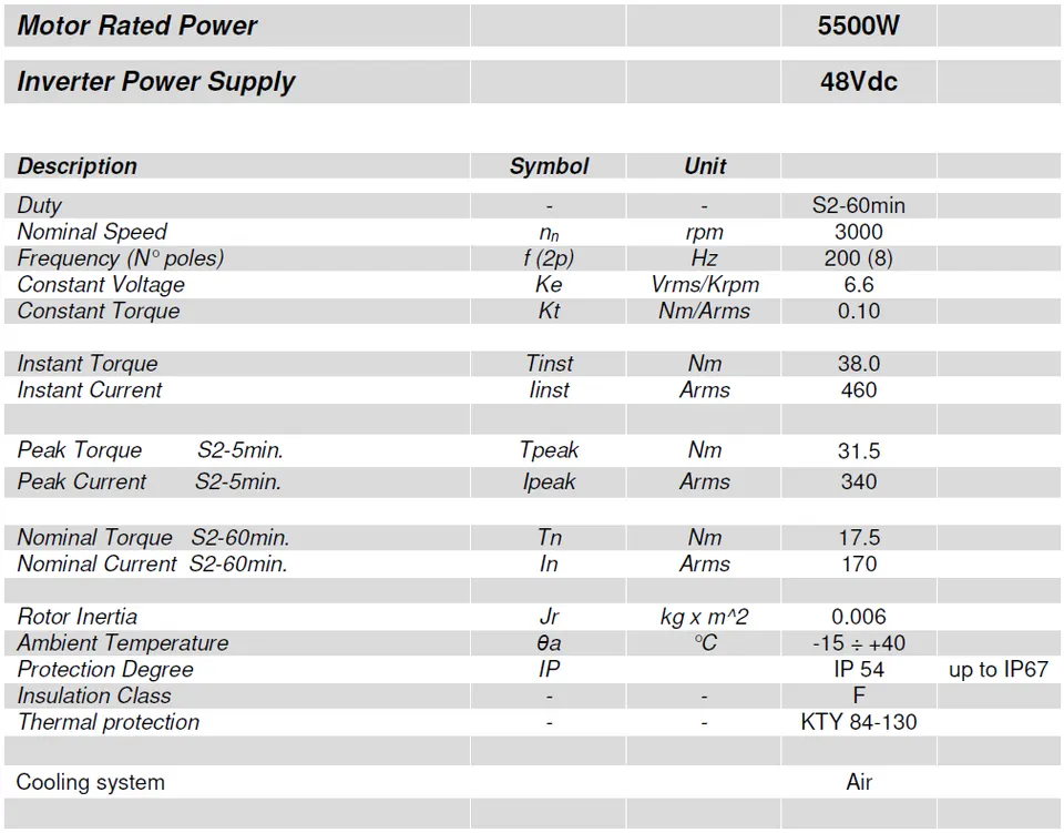
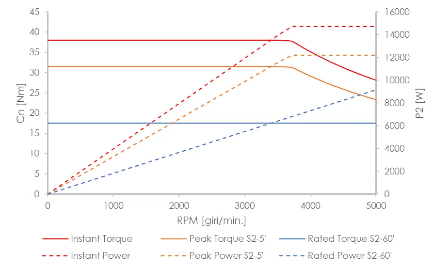
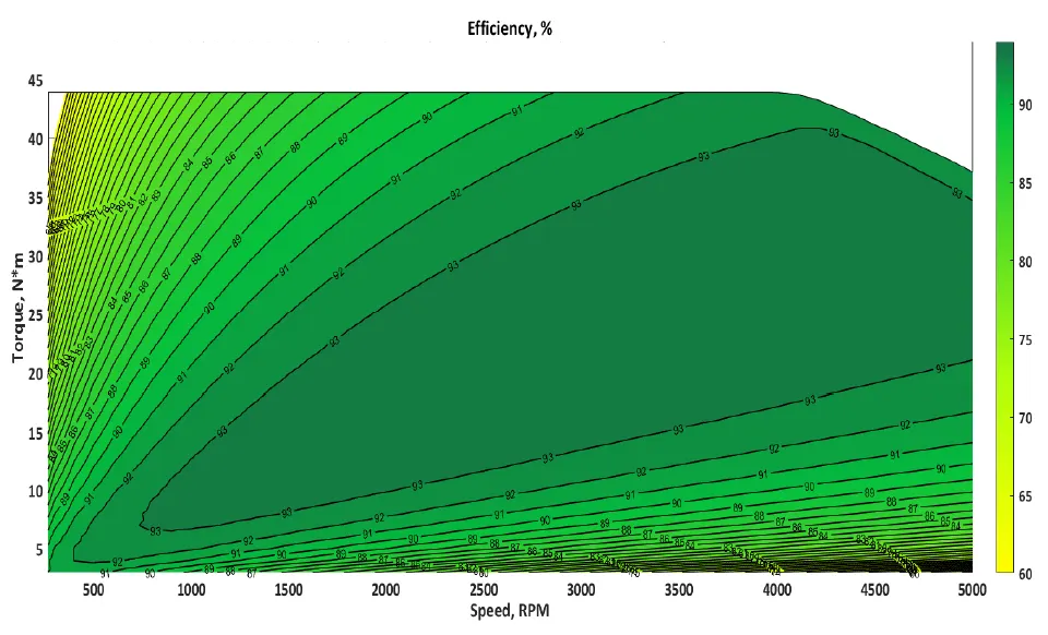
The characteristics of the motors used are provided in the datasheet as follows:
Torque Sensor
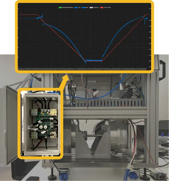
An industrial torque sensor with a measurement range of -50 to 50 Nm is used as the mechanical torque feedback device in this setup. Powered via USB, the sensor comes with software capable of recording real-time data, which can later be analyzed to assess the test process. An example of the torque measurement graph is shown below.
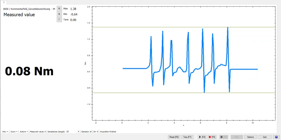
**_Figure 25. Torque sensor software measured graph output example.
_**
Encoders
A shaftless magnetic incremental encoder was used in this setup due to its compatibility with the motor’s back-side mount and its compact design. Below is some information from the encoder’s datasheet for reference.
The encoder is designed for mounting on electric motors or other devices to measure shaft position and speed. Its robust metal housing ensures top-level protection (IP68), high EMC immunity, an extended operating temperature range, and excellent resistance to shock and vibration. Output signals are provided in industry-standard formats, including absolute, incremental, analogue sinusoidal, and linear voltage.
The encoder with an external zeroing feature allows the zero position to be set using a zero pen and operates on a 5 V supply voltage. In its base configuration, the encoder offers resolutions up to 14 bits (16,384 counts per revolution), maintains an installation air gap of ±0.1 mm, and is priced economically.
The encoder supports binary resolutions ranging from 5 to 12 bits, features a wider installation air gap tolerance of ±0.5 mm, and is more cost-effective than the base configuration.
Features:
- High-speed operation up to 60,000 rpm
- Programmable resolution up to 14 bits (16,384 counts/rev)
- Industry-standard absolute (SSI, BiSS C), incremental, and analogue output formats
- Accuracy to ±0.5°
- Power supply options: 5 V or 24 V
- Supports up to 64 poles for commutation
Benefits:
- Low-cost solution for OEM integration
- Exceptional shock and vibration immunity, sealed to IP68
- Non-contact, frictionless design for reliability
- Simple and straightforward installation
- Fully RoHS compliant
Couplings
Used to connect the motor and sensor shafts on both sides, the couplings consist of two parts separated by a spring steel layer. This design allows for slight angular and axial misalignment between the shafts.
Controllers
The motor controller is one of the key components of the test bench. In some cases, the motor controller can be as crucial a testing unit as the motor or the load itself. In this project, we used two motor controllers with identical power ratings, as both the motor and the load sides are equivalent electrical motors.
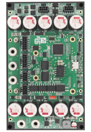
SOLO MEGA is a family of high-power motor controllers that are designed for high-current applications. This product is designed to support various types of electrical motors like DC brushed, Brushless DC and PMSM motors up to 60V with the supply voltage and the continuous current of up to 120 Amps DC or 110 Amps RMS, this will enable SOLO MEGA to be utilized in wide range of products and projects and eventually speeding up the developments and time to market for its users.
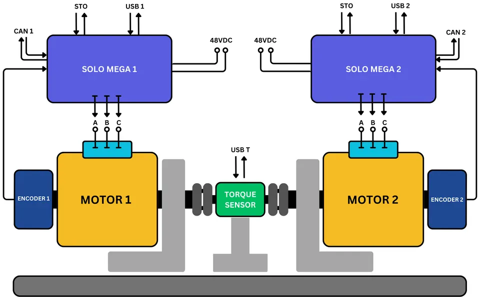
SOLO MEGA can be commanded in two different ways, either by sending Analogue voltages or PWM pulses which is called Analogue Mode, or totally by sending Digital data packets through isolated UART, isolated USB or isolated CAN bus lines. This will give a high flexibility in terms of system setup to the users and they can choose the best way to wire up their systems using SOLO.
The main features of SOLO MEGA are listed as below:
- Wide input voltage supply range from 8V to 60V
- The continuous output current of 120 Amps DC or 110 Amps RMS
- Capable of controlling DC brushed, BLDC and PMSM motors
- Dual Core with parallel processing architecture
- Isolated CAN, USB and UART Communications
- Isolated STO(Safe Torque off) for safe emergency stops
- Active Brake Chopper with selectable activation voltage using an external resistor
- Extremely fast F.O.C loop-rate up to 140kHz (7µs complete execution time)
- Over-current, Over-voltage, Over-Temperature and Under-voltage Protection
- Selectable output PWM switching frequency from 8kHz to 80kHz
- Automatic self-tuning and identification of Motor parameters
- Closed-loop Torque, Speed or Position control
- Advance Field Oriented Control
- PWM and Analogue voltage input for Controlling Speed and Torque
- Pure Analogue feedbacks output for Speed and Torque
- Optically isolated Encoder and Hall Sensor Input with up to +12V supply
- +5V/1A (5W) and +12/0.25A(3W) outputs to supply external modules
- 2.6mA current consumption in sleep mode
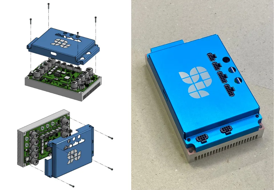
Additionally, it should be noted that, to prevent mechanical damage during operation, the controllers were enclosed in industrial lightweight aluminum covers, as shown in the image below.
Control Units
Control UnitsAs previously mentioned, the test bench features two control panels, which can be broadly categorized into the power input panel and the data output panel. The details of the control elements will be explained further below.
Power Input Panel
The power input panel includes the following control elements:
- Main DC+/- Inlets: Industrial high-current DC connectors capable of conducting up to 200A.
- AC Input Socket: Standard IEC C14 inlet socket with a 2m power cord to supply peripheral control units in the machine.
- AC Power Switch: Controls the main AC power supply, turning it on or off.
- DC Power ON Green Button + LED: Activates the main DC power supply lane.
- DC Power OFF Red Button + LED: Deactivates the main DC power supply lane.
- Emergency STOP Swift Release Red Button: Cuts off the supportive 24VDC lane, shutting down the main DC power supply and preventing it from being reactivated until the STOP button is released.
Data (Output) Panel
The data output panel includes the following elements:
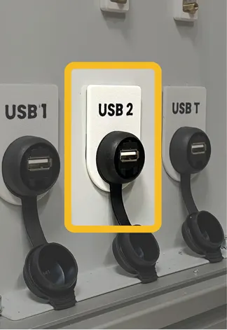
- USB Output: An industrial panel-mount USB socket used to connect to all components, including the motor controller, load controller, and torque sensor.
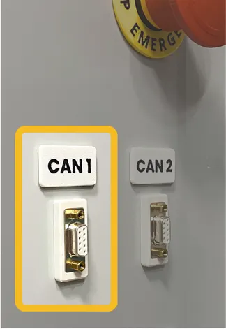
- CAN In/Out: DB9 terminals for controlling the motor and load controllers.
- STO Red Swift Release Button + Lamps: A 16mm industrial-standard button accompanied by two indicator lamps. The button cuts off the STO lane, preventing the SOLO MEGA from injecting current into the motor power connectors. The orange lamp indicates that STO is ON, meaning the Safe Torque Off function is engaged. Conversely, the white LED shows that STO is OFF, allowing the motor to run.
- FAN: An additional exhaust control switch that turns the fans on and off, ensuring proper ventilation of the chamber.
- Emergency STOP Swift Release Red Button: Cuts off the supportive 24VDC lane, shutting down the main DC power supply and preventing it from being reactivated until the STOP button is released.
Safe Torque Off line and chamber cover limit switch
As explained earlier, the “Safe Torque Off” (STO) is a hardware-level protection mechanism that reliably disconnects the energy supply to the motor in your application. For proper operation of SOLO MEGA, providing STO wiring is mandatory.
The STO uses negative logic, meaning that when the STO lines are powered to a high state (e.g., +5V), the unit activates the power electronics controlling the motor. Conversely, when the STO pins are left open or grounded (e.g., connected to ground), the unit stops supplying current to the motor, causing it to stop according to its natural time constant.
In this project, the STO line passes through the control panel’s STO button (via Normally Closed contacts) and the safety cover’s limit switch (via Normally Open contacts). This setup ensures that while the cover remains closed and the STO button is not pressed, the STO function is disengaged, allowing the motor controllers to operate freely. However, if either of these elements changes state—such as the cover being opened or the button being pressed—the STO function engages, cutting the motor’s power supply and stopping the motors. Additionally this will be explained in the control logic and electrical diagrams chapter.
Control Logic and Electrical Diagrams
Triple safety
With the main power source limited to 200A, it is essential to maintain proper control over its usage. The most practical approach to designing such control logic is to utilize multiple power sources operating simultaneously within a single machine. In this test bench, three separate power networks are implemented, which will be explained in detail in the following subchapters.
AC power:
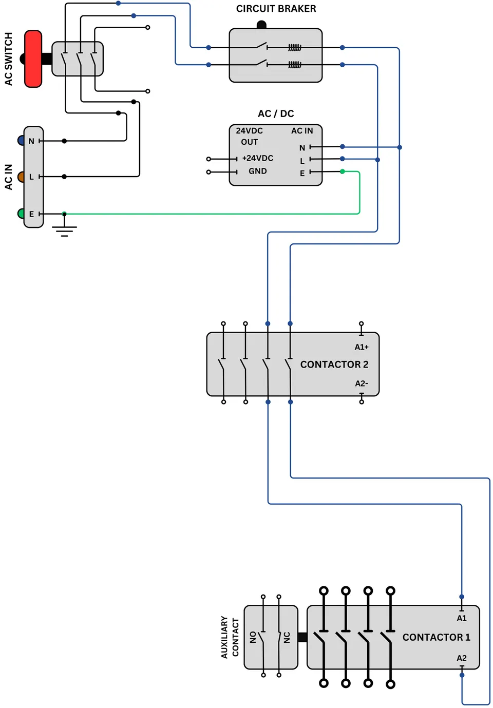
The AC power serves as the main supportive power source, supplying the actuating coil of the general DC power contactor and the AC-DC converter that generates 24VDC for other components. The AC power input features a standard IEC C14 inlet socket with a 2m power cord. For safety, the earth wire is connected to the aluminum frame and the electrical panel within the control cabinet and is not interrupted by the AC switch.
The AC switch controls both the live and neutral lines, which then pass through a circuit breaker equipped with a current leakage detection sensor. If an AC current leakage occurs anywhere in the circuit, the circuit breaker disconnects the power supply to prevent electrical hazards. The overall schematic is illustrated in the diagram below.
24VDC and Self-Holding Relay logic:
The 24VDC power supply is used in the machine as it is one of the most common standards in industrial applications. It provides electrical energy to activate the control relays for the fan, the STO functions of both motor controllers, and the secondary power contactor, which serves as the actuating unit for the main DC power contactor. Additionally, all control lamps and buttons on the control panels are powered by 24VDC, ensuring safety for operators, even if some control elements malfunction.
The 24VDC section of the electrical diagram, together with the previously discussed AC section and the self-holding relay logic, will be explained and illustrated in the paragraphs below.
The concept of self-holding relay logic can be divided into several key steps: activating the self-holding scheme, deactivating it, adding safety features, and providing state feedback (using indicator lamps). This concept is illustrated and explained using the sections of the diagrams provided below.
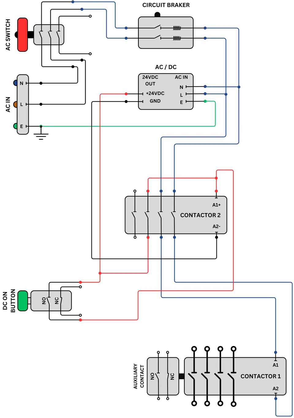
Step 1 – Activation:
To activate Contactor 2, its actuating coil must be supplied with 24VDC, which is achieved by pressing the green button “Main DC On” on the operator panel. Once activated, the normally open (NO) contacts of Contactor 2 close simultaneously. Two of these contacts supply AC power to Contactor 1, while one of the remaining contacts supports the coil voltage of Contactor 2 itself, maintaining its engagement and holding both Contactors 1 and 2 in an engaged state by providing 24VDC to the actuating coil of Contactor 2.
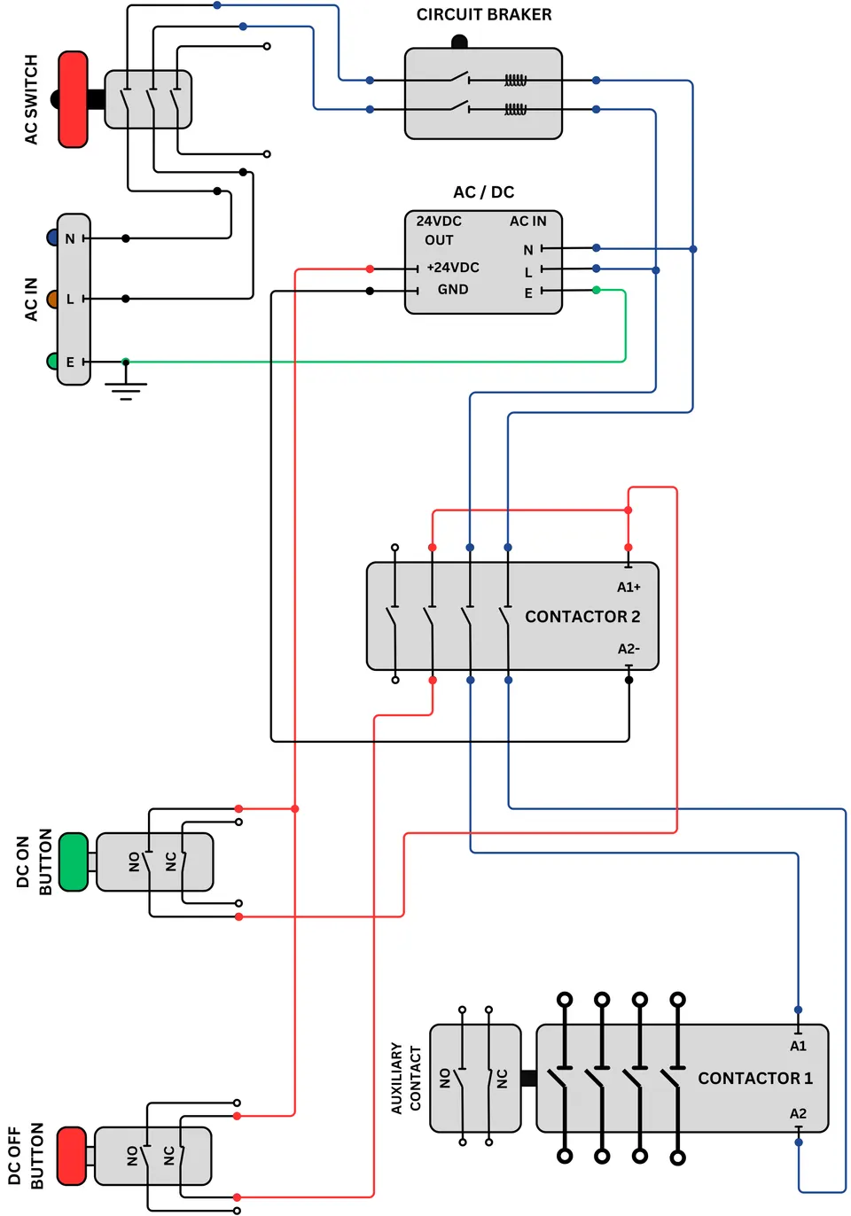
Step 2 – Deactivation:
To ensure the ability to deactivate Contactor 2, its supporting 24VDC line passes through the normally closed (NC) contacts of the red button “Main DC Off”. When this button is pressed, the supportive 24VDC line is interrupted, causing Contactor 2 to disengage and simultaneously cut AC power to the actuating coil of Contactor 1. This setup creates a self-holding relay logic, where Contactor 2 controls Contactor 1.
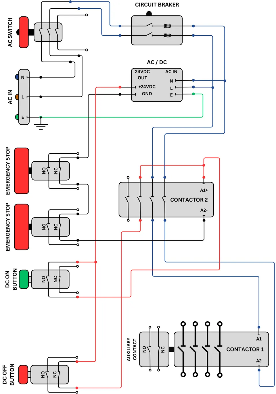
Step 3 – Safety:
Two swift-release red safety buttons are included in the circuit to enhance safety. These buttons cut the ground (GND) line of the actuating coil of Contactor 2, preventing it from engaging while either button is pressed.
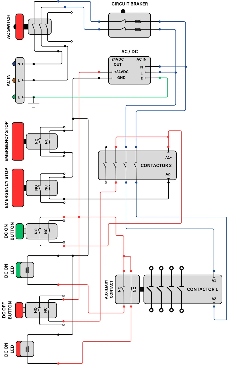
Step 4 – State Lamps:
Additionally, the system features two indicator lamps – red and green – to provide status information about the main DC power. These lamps are connected to the residual contacts of Contactor 1 as follows:
- The green lamp is powered by the NO contact of Contactor 1, meaning it lights up only when the main power contactor is engaged.
- The red lamp is connected to the NC contact of Contactor 1, indicating the OFF state of the main power contactor.
A full self-holding relay logic electrical diagram used in this machine is provided in the Figure below.
Why Self-Holding Logic?
An additional safety feature of this approach lies in the design, where the main power switch remains in the Normally Open position until the operator actively turns it on. This ensures that whenever the machine is turned off using the AC mechanical switch, in the event of a circuit breaker issue, or due to a general AC power line failure, the contactor responsible for the main power supply will automatically disengage its contacts, cutting power to the drive units. This mechanism provides an extra layer of protection against unintended power delivery.
Safe Torque Off and Peripheral Safety:
The schemes above illustrate how the main power of the entire system is controlled. However, there are secondary elements that enable safe and convenient operation of the machine without disconnecting the main power supply. These features allow the operator to change data wires, measure temperature, or adjust mechanical components in the working area without unnecessary power interruptions.
For this purpose, the STO (Safe Torque Off) function of the SOLO MEGA controller is utilized. It ensures that no mechanical motion occurs when the STO button is pressed or the chamber cover is opened, providing an additional layer of safety during maintenance or adjustments.
The diagram can be divided into several steps to simplify the explanation. These steps include: connecting the STO relays for the two controllers, establishing the logic for the STO state indicator lamps, and integrating the fan control to prevent overheating.
STO for Two SOLO MEGAs:
In this machine, the STO function is wired to a safety relay using the internal +5V non-isolated supply voltage, as shown in the figure below. This internal supply voltage connects directly to the STO inputs. The safety relay can be controlled by external commanding devices for enhanced safety and reliability.
In our setup, these commanding devices include the STO Swift Release red button and the chamber cover limit switch, which are connected in series to supply the relays STO 1 and STO 2 and ensure proper operation and safety compliance.
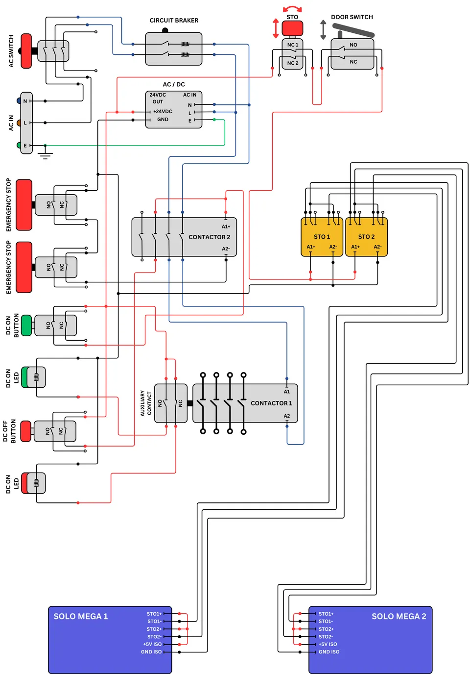
STO State Indicator Lamps:
The indicator lamps are connected to an additional relay that operates in parallel with the two relays dedicated to the STO function. This setup supplies +24VDC to the white lamp, which is connected to the relay’s Normally Open (NO) contact. The white lamp illuminates when the STO relays are engaged, indicating that the controllers are allowed to provide torque to the motors. Conversely, when the relays are disengaged, the orange lamp lights up to indicate that the Safe Torque Off (STO) function is active, preventing the controllers from injecting current into the motors.

FAN Control:
The fan control ensures a safe and reliable connection for two high-power fans operating on 24VDC. This setup includes an additional relay (FAN) controlled by a panel-mounted switch, as illustrated in the diagram below. The two fans are connected to +24VDC through the relay, with their GND wires shared and connected to the GND of the power supply. The relay is activated or deactivated by the panel switch, which supplies power to engage or disengage the relay.
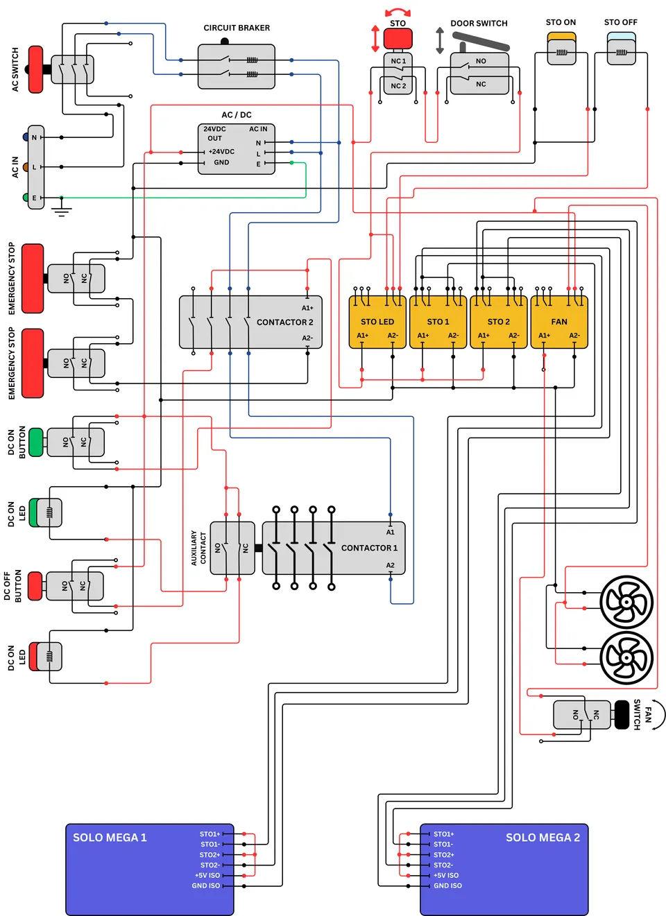
Main Power and Residual Data Cables:
With all systems connected and the control logic functioning as designed, the next step is to route the main power cables and complete the diagram. In this setup, a 48VDC external power supply (or any voltage between 8 and 60VDC, as specified in the SOLO MEGA manual) is connected via industrial high-current DC connectors mounted on the power control panel of the motor test bench. These wires are routed to Contactor 1, as illustrated in the figure below.
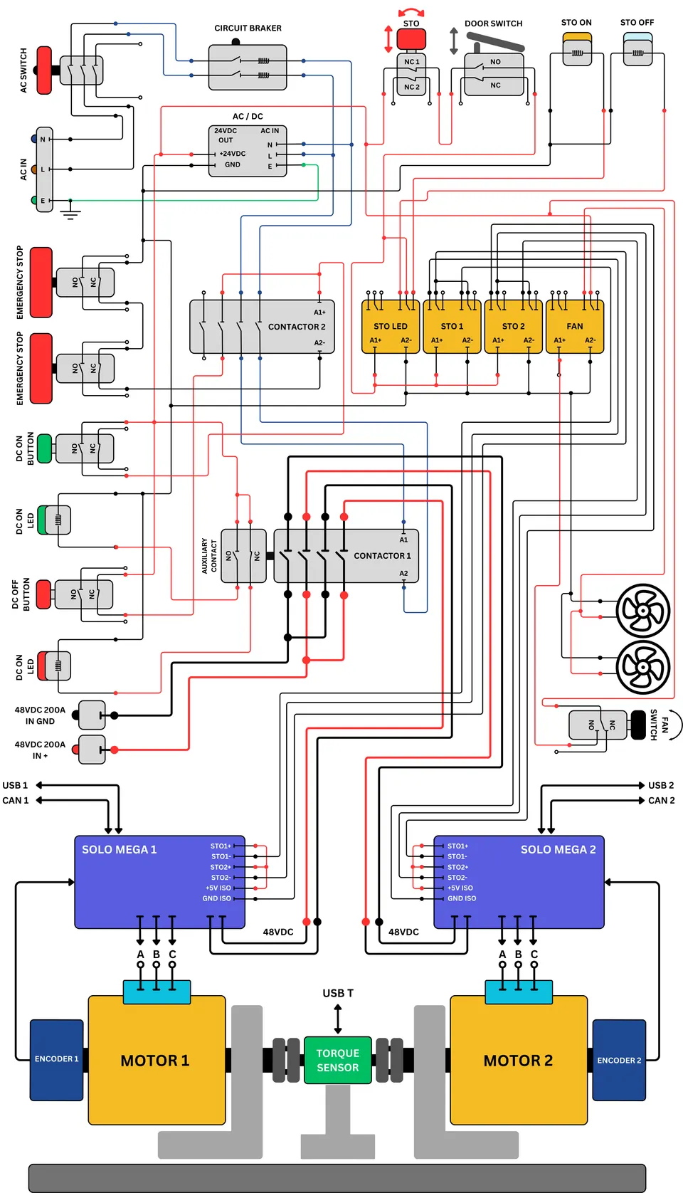
CAN communication line:
For the CAN line communication cable, the J7 connector of SOLO MEGA was used, as shown in the figure below. A shielded multi-wire cable was connected to the GND-ISO, ISO-CAN-H, and ISO-CAN-L terminals on the SOLO MEGA controller. On the other side, a DB9 panel-mount connector was wired to ensure compatibility with KVASER CAN-converting devices.
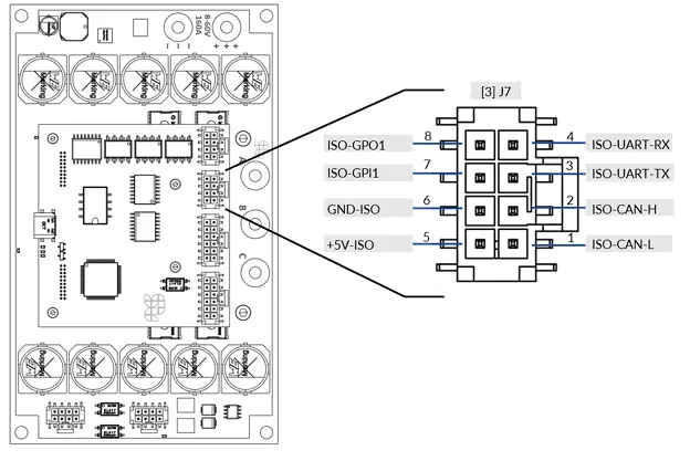
USB:
For USB connections, shielded cables with a ferromagnetic ring at the end were used to minimize noise interference. These cables are routed through dedicated cable trenches, positioned away from the main contactors and relays to avoid electromagnetic interference. They connect the controllers and the torque sensor to their respective USB panel sockets.
Encoder:
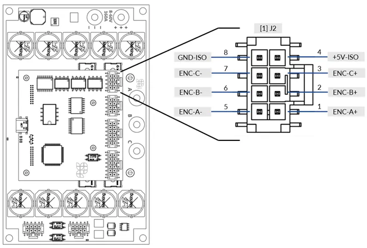
For the encoder feedback connection, the J2 connector of the SOLO MEGA was utilized. A magnetic shaftless incremental encoder was employed and connected as shown in the connector map below. For more details about encoder types and their connections, please refer to the user manual.
Custom Solutions and Orders
SOLO Motor Controllers offer custom test benches designed to adapt to unique needs or Standard Solutions. From specialized hardware setups to advanced testing features, ensuring each solution is both practical and efficient.
A Solution That Fits
SOLO’s Test Benches are built with flexibility in mind, tailored to match specific applications. Whether for small-scale testing or more demanding projects, they combine reliability, ease of use, and precision.
End-to-End Support
SOLO takes care of everything:
- Custom Design & Assembly to suit any requirements.
- Technical Assistance for smooth operation.
- Worldwide Delivery to ensure solutions arrive wherever needed.
With SOLO’s custom test benches, users can approach motor testing with confidence, knowing the tools are designed around their needs. Those interested can reach out to explore the possibilities of a tailored solution.
Conclusion
The final result is a compact, mobile motor test bench ideal for laboratory tests, offering the capability to control the process via CAN lines. This allows for parameter adjustments and data recording for further analysis.
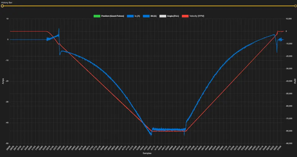
A key component of this project is the Motion Terminal online software, which provides real-time monitoring of motor and controller behavior. It also allows users to record and export data for detailed analysis, including mechanical torque graphs.
Refer to the figure below for an example of the Motion Terminal in operation. Watch our video about the test bench, and don’t forget to subscribe to our channel to learn more about motor control.
Products in this article
Related articles
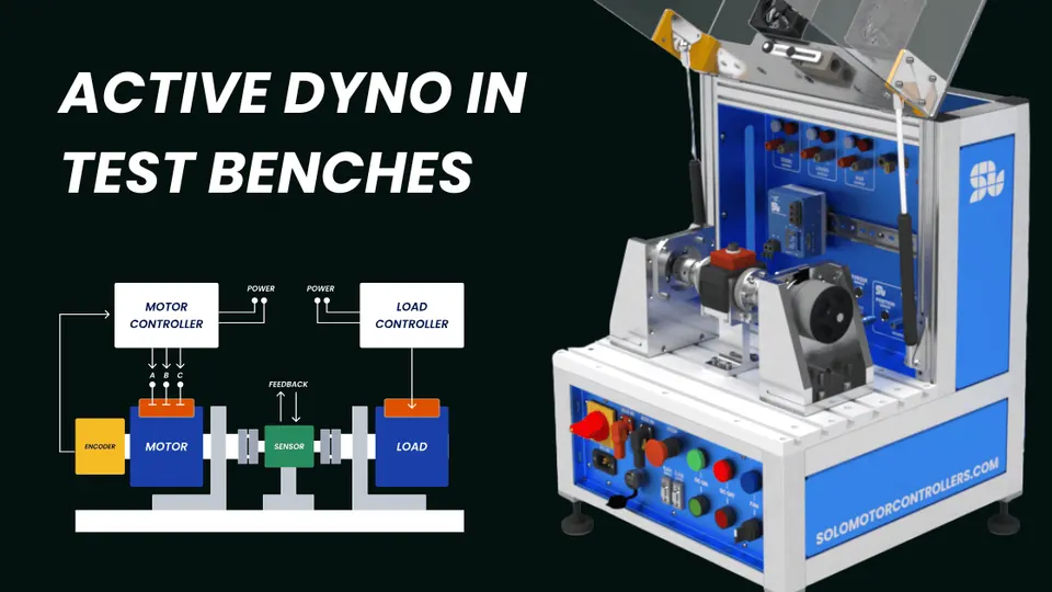
Active Dyno in Test Benches
Test EV, BLDC, and servo motors with precision using Active Dyno benches powered by SOLO Motor Controllers for bidirectional control and R&D.

Test Bench for Thermal Stress Testing
Discover how thermal stress test benches improve motor reliability, safety, and efficiency by simulating real-world heat conditions.
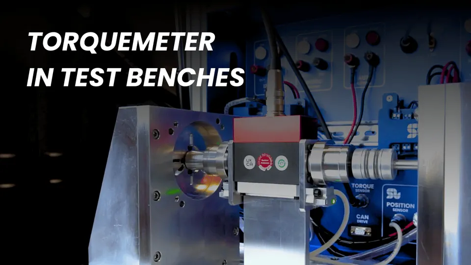
Torquemeter in Test Benches
Discover why torquemeters are essential for accurate motor testing and how SOLO Motor Controllers simplify torque-driven test bench setups.
