
Automatic Motor Identification: How SOLO Measures R, L and Kt
Introduction
To run a motor under field-oriented control, you need three numbers: phase resistance, phase inductance, and the torque constant. Get one of them wrong by 30% and the current loops fight the motor instead of driving it. The result is rough torque, audible noise, or a startup that never spins. Most engineers hunt for these values in a datasheet, then type them in by hand and hope they are right.
Automatic motor identification removes that step. SOLO injects test signals into the motor, measures how it responds, and computes R, L and Kt on its own. You connect the motor, start the routine, and read the values a few seconds later. No datasheet, no math, no code. This article shows what each parameter does, how the routine works in Motion Terminal, and what to check when a result looks wrong.
Why R, L and Kt Matter for FOC
Field-oriented control, or FOC, regulates the current in the motor windings to produce smooth torque. The current loops use a model of the motor, and that model is built from three parameters. If the values are off, the loop gains are off too, so the controller either responds too slowly or overshoots into noise. This is why identification comes before tuning, not after. The same model also underpins sensorless operation, where the controller estimates rotor position from the motor itself. You can read more on that in our guide to sensorless control.
Phase Resistance (R)
Phase resistance is the DC resistance of one motor winding, measured in ohms. It sets how much voltage you spend just to push current through the copper, and it drives the proportional term of the current loop. A low-resistance motor reaches its target current fast, so the loop gain must follow. Resistance also rises with temperature, so a value measured cold will read a little lower than the same motor when hot.
Phase Inductance (L)
Phase inductance describes how the winding resists a change in current, measured in henries or millihenries. It sets the electrical time constant of the motor and, with resistance, defines the bandwidth the current loop can reach. Low-inductance motors, common in drones and high-speed spindles, change current very fast and are the hardest to identify and control. Higher inductance smooths the current ripple but slows the response.
Torque Constant (Kt)
The torque constant, Kt, links current to torque. It tells you how many newton-meters you get per amp of quadrature current. Once SOLO knows Kt, it can translate a torque command into a precise current target, which is the whole point of running torque control in the first place. Kt is also the mirror of the back-EMF constant Ke, so the same measurement that gives you torque per amp also tells the controller how the motor generates voltage as it spins.
Takeaway: R sets loop gain, L sets loop speed, and Kt turns current into torque. FOC needs all three to be right.
What “No Programming” Really Means
Many drives ask you to find R, L and Kt yourself. You open the motor datasheet, copy the numbers into a configuration tool, and convert units if the datasheet uses different ones. If the motor is unbranded or rewound, there is no datasheet at all, so you reach for a bench meter and an oscilloscope. That is slow, and a single typo can send the motor into a fault on first power-up.
No programming means none of that. You do not write code, you do not script a measurement sequence, and you do not hunt through a PDF. SOLO measures the real motor in front of you, which is more accurate than a datasheet anyway, because it captures your exact wiring, temperature, and any tolerance in the build. The routine is a button, not a project. This is the same philosophy behind the rest of Motion Terminal motor setup, where configuration is done through the interface, not through firmware edits.
Running Automatic Identification in Motion Terminal
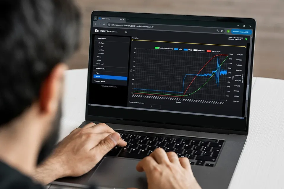
Identification runs entirely from Motion Terminal, the desktop app that connects to the controller over USB. The flow is short: prepare the motor, start the routine, then save the values it returns. Here is each part.
Prerequisites Before Identification
Get a few things right before you press start, because they decide whether the result is trustworthy.
- Free the shaft. The motor should spin freely, with the load disconnected or at least decoupled. A coupled load distorts the inductance and Kt measurement.
- Set the power supply. Use the correct bus voltage and a current limit high enough for the test pulses, but not so high that a wiring fault becomes dangerous.
- Set the motor type and pole count. Tell SOLO whether the motor is BLDC, PMSM, or another type, and enter the number of pole pairs. Kt and the electrical angle depend on it.
- Check the phase wiring. All three motor phases must be connected to the right terminals. A swapped or loose phase is the most common reason a result looks wrong.
Step-by-Step Identification Routine
With the motor ready, the routine itself is simple.
- Open the identification or motor setup view in Motion Terminal.
- Confirm the motor type and pole pairs you set earlier.
- Start the identification routine.
- SOLO injects controlled voltage and current signals into the windings. It measures the current response to compute resistance and inductance, and it spins or energizes the motor briefly to find Kt.
- Wait for the routine to finish. It typically takes a few seconds, longer for very low-inductance motors that need finer measurement.
You do not adjust anything during the run. The controller drives the test, reads the response, and stops on its own.
Reading and Saving the Measured Values
When the routine ends, the measured R, L and Kt appear in the parameter fields. Look them over before you save. Resistance in the milliohm-to-low-ohm range and inductance in tens to hundreds of microhenries are typical for small BLDC and PMSM motors, though your motor may differ. If the numbers look reasonable, write them to the controller configuration so they survive a power cycle. From there you can move on to tuning the current and speed loops, and watch the live signals while the motor runs to confirm the model holds up under load.
Takeaway: prepare the motor, run one routine, check the values, and save them to config.
When Identification Fails or Looks Wrong
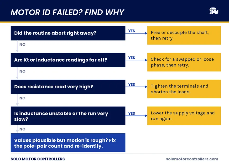
Most failed identifications trace back to a handful of causes. Work through them in order before you blame the routine.
| Symptom | Likely cause | Fix |
|---|---|---|
| Routine aborts or faults immediately | Load still coupled, or shaft cannot move | Decouple the load, free the shaft |
| Kt or inductance reads far off | One motor phase swapped or loose | Recheck all three phase connections |
| Resistance reads very high | Loose terminal or thin extension wire | Tighten and shorten the power leads |
| Inductance unstable, run very slow | Very low-inductance motor near the limit | Lower the supply voltage, retry |
| Values plausible but motor still rough | Wrong pole-pair count entered | Correct pole pairs, run again |
A motor driven into magnetic saturation by too much test current can also report a lower inductance than it has at normal load. If the result feels wrong, lower the current limit and run it again. When a fault code appears during the routine, read it before retrying, since it usually points straight at the cause.
Manual Override: When to Enter Values Yourself
Automatic identification covers most motors, but a few cases call for entering values by hand. If you have trustworthy datasheet numbers for a known motor, you can type them in and skip the routine, which is handy on a production line where every motor is identical. Induction motors are the other case: an AC induction motor has no permanent magnets, so it has no fixed Kt, and its parameters are modeled differently from a brushless motor. For those, follow the induction-specific setup rather than the brushless identification flow. Manual entry is also a fine sanity check. Run the routine, compare its result to the datasheet, and you learn something either way.
How SOLO Handles Motor Identification
SOLO is built to handle motor identification inside Motion Terminal, so commissioning an unfamiliar motor stays quick. The controller can measure R, L and Kt for DC, BLDC, and PMSM motors from the app, with no firmware edits and no separate bench instruments. The aim is to support the engineer who has a motor on the desk and a deadline, not to assume a clean datasheet always exists. You can see how identification fits the wider setup flow on the SOLO Motion Terminal page.
Conclusion
FOC needs three motor parameters to work: phase resistance, phase inductance, and the torque constant. Automatic identification measures all three from the real motor, so you skip the datasheet hunt and the manual math. Free the shaft, set the motor type and pole pairs, run the routine, check the values, and save them. If a result looks wrong, the cause is usually a coupled load, a swapped phase, or the wrong pole count, not the motor itself. To try it on your own motor, connect a controller and open Motion Terminal.
FAQ
Do I need to run identification every time I power on?
No. You run identification once per motor. The measured R, L and Kt are saved to the controller configuration and persist across power cycles. Run it again only if you change the motor, rewire the phases, or move to a very different operating temperature.
What if I already know R, L and Kt from the datasheet?
You can enter them by hand and skip the routine. That works well on a production line with identical motors. Keep in mind that a measurement on the real motor captures your exact wiring and tolerances, so it is often more accurate than a generic datasheet value.
Does identification work on induction motors?
The brushless identification routine targets DC, BLDC, and PMSM motors. An induction motor has no permanent magnets and no fixed Kt, so its parameters are modeled differently. Use the induction-specific setup for those motors rather than the brushless flow.
Why are my measured values different from the datasheet?
Small differences are normal. Resistance rises with temperature, and inductance changes with current as the iron approaches saturation. The routine measures your actual motor at its current state, while a datasheet lists nominal values at a reference condition. A large gap usually points to a wiring or pole-pair issue instead.
Related articles
PWM Frequency Selection for Low-Inductance Motors
How to choose the PWM switching frequency on SOLO, why low-inductance motors need a higher frequency, and the trade-offs with heat and ripple.
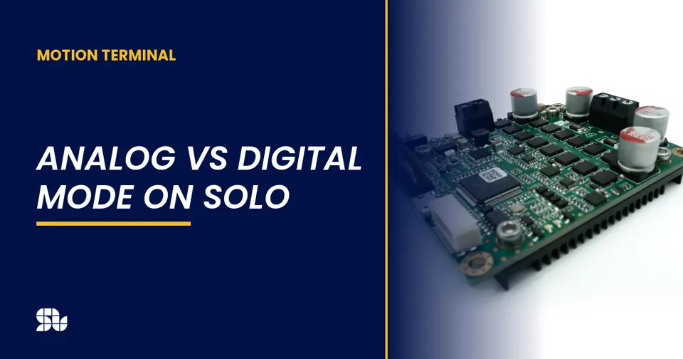
Analog vs Digital Mode on SOLO: When to Use Which
Analog or digital command mode on SOLO? Compare analog inputs vs UART, USB and CAN control to pick the right command interface for your project.
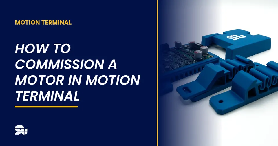
How to Commission a Motor in Motion Terminal: Step by Step
A step-by-step guide to commissioning a motor with SOLO Motion Terminal: connect, identify, calibrate, and run your first closed-loop spin.
