
High Speed Observer (HSO) Sensorless: How It Works and Filter Tuning
Introduction
Above a few hundred RPM, a motor’s back EMF grows large enough to read the rotor position straight from the phase voltages, with no encoder at all. That is the job of the High Speed Observer (HSO): it estimates rotor angle and speed from the back EMF, so a sensorless drive stays smooth and stable at high RPM.
The catch is the observer filter. Get its cutoff frequency right and the estimate is clean and quick. Get it wrong and the motor lags, chatters, or stalls. This article explains what the HSO does and how to tune that one filter cutoff in Motion Terminal.
What the High Speed Observer Does
The HSO is a model of your motor that runs in software every control cycle. It watches the measured phase currents and voltages, predicts the back EMF the motor should be producing, and from that back EMF it works out where the rotor is and how fast it turns. No position sensor is involved.
Back EMF rises with speed. At a standstill it is zero, which is why an observer alone cannot find the rotor at zero speed. Once the motor spins fast enough, the back EMF signal is strong and the angle estimate becomes reliable. That is the speed range the HSO owns: mid to high RPM, where the signal is loud and clean.
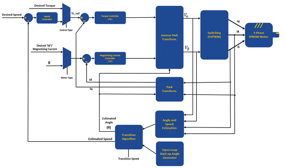
At zero and very low speed, SOLO uses a different method, Zero Speed Full Torque (ZSFT), which injects a small high-frequency signal to find the rotor without back EMF. For the background on the sensorless algorithm and back EMF itself, see sensorless BLDC and PMSM control and back EMF.
Takeaway: the HSO reads position from back EMF, so it works once the motor is spinning, not from rest.
Observer vs High Frequency Injection
Sensorless control is not one method but two, each for its own speed band. High frequency injection finds the rotor at low speed by injecting a test signal and reading how the motor responds. The observer takes over higher up, where back EMF is strong. The drive blends from one to the other as speed rises, so the handover is smooth and you never lose the angle.
| Method | Speed regime | Signal used | When it takes over |
|---|---|---|---|
| High frequency injection | Zero to low RPM | Injected HF carrier + saliency | From standstill up to the crossover |
| High Speed Observer (HSO) | Mid to high RPM | Motor back EMF | Above the crossover speed, the rest of the range |
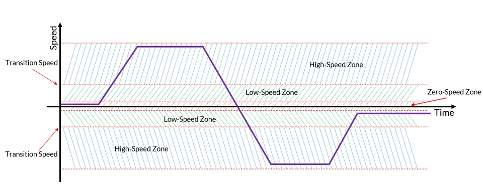
The two methods overlap around the crossover speed, where the drive hands control from injection to the observer. A well-set crossover keeps torque steady through that transition.
Takeaway: injection handles standstill, the observer handles speed, and the drive blends between them.
The Observer Filter and Why Cutoff Matters
The raw back EMF estimate is noisy, so the observer runs it through a low-pass filter before it trusts the angle. The filter cutoff frequency sets where that filter starts to attenuate. It is the single most important knob for high-speed sensorless behavior, and it is a balance between two failures.
A low cutoff filters hard and gives a smooth but slow estimate. A high cutoff filters little and gives a fast but noisy estimate. Your job is to find the cutoff that is fast enough to keep up with the rotor, yet smooth enough to ignore the noise.
Cutoff Too Low: Lag and Instability
If the cutoff is too low, the filter is too slow. The angle estimate lags behind the real rotor, because the filter delays the signal. At low speed that lag is small, but as RPM climbs the rotor moves further during each delay, so the error grows. Past a point the lag is large enough that the current is applied at the wrong angle, torque drops, and the loop can lose sync and stall.
So a cutoff that feels safe and quiet at mid speed can make the motor unstable when you push the RPM up.
Cutoff Too High: Noise Passes Through
If the cutoff is too high, the filter lets noise through. PWM switching ripple, current sensor noise, and inverter dead-time all show up in the estimated angle. The result is a jittery angle estimate, audible whine, ragged current, and extra heat. The motor may run, but it runs rough, and the noise can trip protections under load.
Takeaway: too low means lag and stalls at high RPM, too high means noise and rough running. Tune for the middle.
Tuning the Filter Cutoff in Motion Terminal
You tune the observer cutoff the same way you tune any loop: start safe, push the limit, then back off. The steps below use the live monitor in Motion Terminal so you watch the estimate instead of guessing.
Step 1: Baseline at Mid Speed
Start at a mid speed your motor reaches easily, for example a quarter to a third of its rated RPM. Spin it under no load and set the observer cutoff to its default or a moderate value. Confirm the motor runs and the estimated speed is steady. This is your baseline, a known-good starting point you can always return to.
Step 2: Push Speed and Watch the Estimate
Raise the speed command toward your target RPM in steps. At each step, watch the monitor: compare estimated speed against the commanded speed, and watch the estimated angle and Iq for jitter. If the estimate starts to lag or the motor loses sync as you climb, your cutoff is too low. Raise it. If the angle gets noisy and Iq rattles, the cutoff is too high. Lower it. Move in small steps and keep the motor inside safe limits.

A clean estimate tracks the real speed closely with little noise, like the sensorless trace above sitting on top of the encoder one.
Step 3: Trim for Smoothness Under Load
No load is the easy case. Now apply the load the motor will see in the application and repeat the top-speed test. Load changes the current and the back EMF, so the cutoff that looked perfect with a free shaft may need a small trim. Aim for a steady Iq and a quiet, stable angle estimate at full speed and full load. When the motor holds speed smoothly through load steps, the cutoff is right.
Takeaway: baseline safe, push to find the edge, then trim under real load.
High Speed Sensorless Gotchas
A few motor and drive traits make high-speed sensorless harder, and no filter cutoff fixes them on its own.
Low-inductance motors are the classic one. Low inductance lets current change fast between PWM edges, which adds ripple and noise to the measurements the observer depends on. These motors often need a higher PWM frequency and careful current sensing to stay clean. See low inductance motors for why they are demanding and how to handle them.
PWM frequency also sets your ceiling. The control loop runs once per PWM cycle, so a higher electrical frequency at high RPM needs enough PWM cycles per electrical revolution to keep the angle accurate. A PWM frequency that is too low starves the observer of updates.
Inverter dead-time distorts the voltage the observer assumes it applied. That distortion corrupts the back EMF estimate, most at light load where it is a larger share of the voltage. Dead-time compensation reduces the error.
Takeaway: check inductance, PWM frequency, and dead-time before blaming the cutoff.
How SOLO Supports High Speed Sensorless
SOLO controllers run sensorless FOC across the full range and switch from injection at zero speed to the High Speed Observer at speed, so you generally get one smooth sensorless drive instead of two methods to stitch together. The observer filter cutoff and the other sensorless parameters are exposed in Motion Terminal, with a live monitor that plots estimated speed and current while you tune, so you can set the cutoff by watching the motor rather than by trial and error. You can try the workflow with a controller like the SOLO UNO and the Motion Terminal software.
Conclusion
The High Speed Observer estimates rotor angle and speed from back EMF, so it carries sensorless control through the mid and high RPM range where back EMF is strong. Below that, injection takes over, and the drive blends between them. The one parameter that decides whether high-speed running is smooth or unstable is the observer filter cutoff: too low and the angle lags until the motor stalls, too high and noise makes it run rough. Tune it by starting safe at mid speed, pushing toward your target while you watch the estimate, then trimming under real load. To put it into practice, open the live monitor in Motion Terminal and tune the cutoff against your own motor.
FAQ
What is a high speed observer in sensorless control?
A high speed observer is a software model of the motor that estimates rotor angle and speed from the motor’s back EMF, with no position sensor. Back EMF grows with speed, so the observer works once the motor is spinning at mid to high RPM. At zero and very low speed a different method, signal injection, finds the rotor instead.
How do I choose the observer filter cutoff frequency?
Start from the default at a mid speed under no load and confirm the estimate is steady. Then raise speed toward your target: if the estimate lags or loses sync, raise the cutoff, and if the angle gets noisy, lower it. Finish by trimming the cutoff under real load. The goal is the highest cutoff that still gives a clean, lag-free estimate at full speed.
Why does my sensorless motor get unstable at high RPM?
The most common cause is an observer cutoff that is too low. A low cutoff slows the filter, so the angle estimate lags the real rotor, and that lag grows with speed until the current is applied at the wrong angle and the loop loses sync. Low motor inductance, a low PWM frequency, and uncompensated dead-time make it worse.
Do I still need injection if I use the observer?
Yes, if you need torque from zero or very low speed. The observer relies on back EMF, which is zero at standstill, so it cannot find the rotor from rest. Injection covers zero and low speed, the observer covers high speed, and the drive hands control between them as speed rises. If your application always starts under light load and spins up fast, the observer may be enough, but most loads benefit from both.
Tags:Motion TerminalObserverSensorless
Products in this article

Related articles
Tuning Sensorless Injection (Amplitude and Frequency) on SOLO
How to tune the ZSFT injection amplitude and frequency on SOLO for stable, low-noise sensorless control at standstill and low speed. A Motion Terminal guide.

Closed-Loop vs Sensorless: Choosing Your Feedback Strategy
A decision guide to choosing your motor feedback: sensorless vs encoder vs hall. Match the feedback mode to your speed range, torque and accuracy needs on SOLO.

Zero Speed Full Torque (ZSFT): Sensorless Control from Standstill
How SOLO holds full torque at zero speed without sensors. What ZSFT is, when to use it, and how to set up zero speed sensorless control in Motion Terminal.
