
Build a Mini Motor Dyno Using SOLO
More than 60% of electric motor projects fail at the prototype stage due to lack of proper testing. This simple but powerful insight tells us that motor testing is not optional—it’s essential.
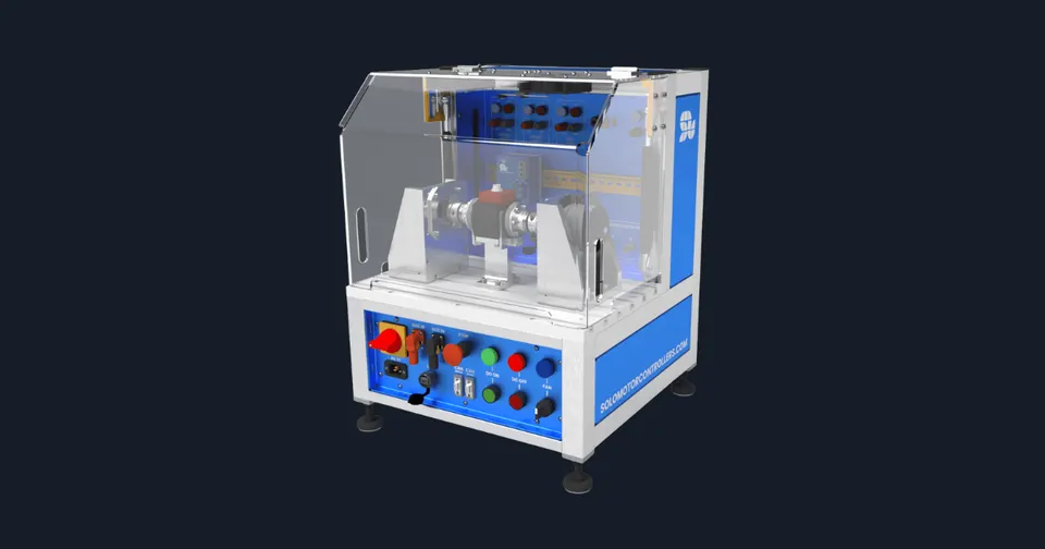
If you’re a robotics developer, a DIY enthusiast, a university engineering student, or part of a startup designing electric vehicles, understanding how your motors perform under load is critical. And the best way to do that? Build a mini motor dyno using the SOLO Motor Controller.
What Is a Mini Motor Dyno?
A mini motor dyno is a small-scale motor testing setup used to measure:
- Torque (Nm)
- Rotational speed (RPM)
- Electrical current (A)
- Voltage (V)
- Mechanical and Electrical Power (Watts)
- Efficiency (%)
- Motor heating and stability under load
Using a motor dynamometer helps you analyze how your motor behaves under different loads, speeds, and control methods. A mini version is compact, budget-friendly, and perfect for labs, home workshops, or prototyping setups.
Why Use the SOLO Motor Controller?
The SOLO Motor Controller is a compact, intelligent, and plug-and-play motor controller that works with:
- DC Brushed Motors
- BLDC Motors
- PMSM Motors
It supports both sensor-based and sensorless Field-Oriented Control (FOC), offering precision, flexibility, and real-time feedback, making it the perfect match for building your own motor dyno.
Complete Guide: How to Build a Mini Motor Dyno Using SOLO
Materials and Components
| Component | SOLO Motor Controller | Test Motor | Load Motor | Torque Sensor | Encoder / Rotational Speed Sensor | Power Supply | Data Logger / SOLO Studio GUI | Mechanical Frame & Couplings | Cooling Fan or Heat Sink |
|---|---|---|---|---|---|---|---|---|---|
| Purpose | Controls and monitors the test motor | Motor under examination | Acts as the brake to simulate load | Measures torque generated by the motor | Tracks the speed of the motor shaft | Powers both the test motor and load motor | For visual monitoring and logging performance data | Mounts and aligns both motors and sensors | Prevents overheating during long test sessions |
Mechanical Assembly and Wiring Overview
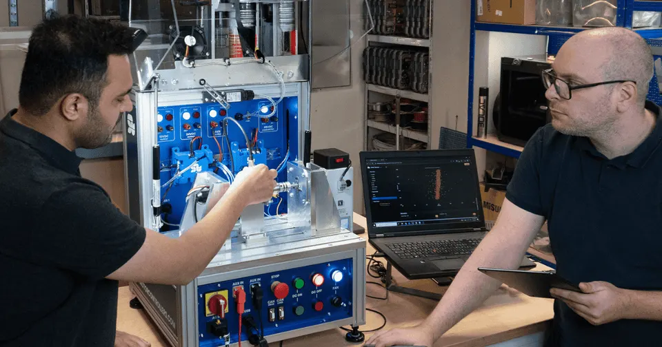
- Mount both motors on the frame: Use stable rigid construction like a T-Slot plate
- Mount a Torque Sensor and attach it between test and load motor shafts using couplings
- Add a Rotational Speed Sensor to test motor shaft
- Connect SOLO Motor Controller to your test motor
- Connect Power Supply to SOLO and load motor (through another SOLO or different driver), check that the power matches voltage/current requirements for both motors
- Make sure that the system has any safety loop to prevent mechanical failures during tests (Use SOLO Safe Torque Off or learn more about safety in our articles)
- Use SOLO Studio GUI via USB or UART to configure parameters and view live data
- For testing use manual control via SOLO GUI or either a specific test profile can be provided using CAN line

Applications of a Mini Motor Dyno with SOLO
| Use Case | Motor Research & Development | Education & Learning | DIY Robotics | EV Prototyping | Quality Control |
|---|---|---|---|---|---|
| How It Helps | Validate performance under load conditions | Perfect for labs and courses on mechatronics or motor control | Helps hobbyists tune motors for mobile robots and drones | Test motors for e-bikes, scooters, and small electric vehicles | Ensure motors meet torque, speed, and thermal criteria |
Advantages of Building a Mini Motor Dyno Using SOLO
| Feature | SOLO Test Bench Software | FOC Sensorless + Encoder Modes | Real-Time Data Monitoring | SOLO Studio GUI | Multi-Motor Compatibility | Safe and Scalable | Cost-Effective |
|---|---|---|---|---|---|---|---|
| Advantage | Works in parallel with load side motor controllers and provides logging and real time data acquisition for such characteristics like: Rotational Speed (RPM), Mechanical Torque (Nm), Consumed Current (A), Lane Voltage (V), Mechanical and Electrical Efficiency (%), Temperature (C) and others | Flexible setup based on budget or precision needs | Adjust control strategies and see immediate feedback | User-friendly interface for beginners and pros alike | Supports DC, BLDC, PMSM motors out of the box | Small form factor, over-current and over-temperature protections built-in | Much cheaper than lab-grade dynamometers |

Dyno Build Challenges (and How to Solve Them)
| Challenge | Mechanical misalignment | Data noise from sensors | Load motor control complexity | Heat buildup in motors or controller | Torque sensor cost or inaccuracy |
|---|---|---|---|---|---|
| Why It Matters | Can cause vibration, which affects test results and damage couplings and motors | Leads to incorrect efficiency readings | Can over-brake or under-brake the test motor | Shortens test time, may damage electronics | May distort performance testing |
| How to Solve It | Use rigid frame and precision mounts | Use shielded cables and grounding techniques | Use matching load motor to allow the test motor show its full performance | Add fans, heat sinks, or even water cooling if necessary | Ensure sensor range matches the measurement limits to prevent over- or under-saturation errors |
Pros and Cons Summary Table
| Pros | Professional-grade motor testing at low cost | Modular and easy to expand | Live monitoring and adjustable parameters | Accurate testing of motor torque and efficiency | Compatible with multiple motor types |
|---|---|---|---|---|---|
| Cons | Requires basic understanding of mechanical system building and electrical wiring | Needs careful alignment to avoid extra mechanical stress | Setup can be time-consuming for absolute beginners | Limited by sensor quality and load motor response | High-speed or high-power testing requires additional safety |
Educational Tip: Understanding Key Motor Dyno Terms
| Term | Torque (Nm) | Rotational Speed (RPM) | Efficiency (%) | Back EMF | Regenerative Braking |
|---|---|---|---|---|---|
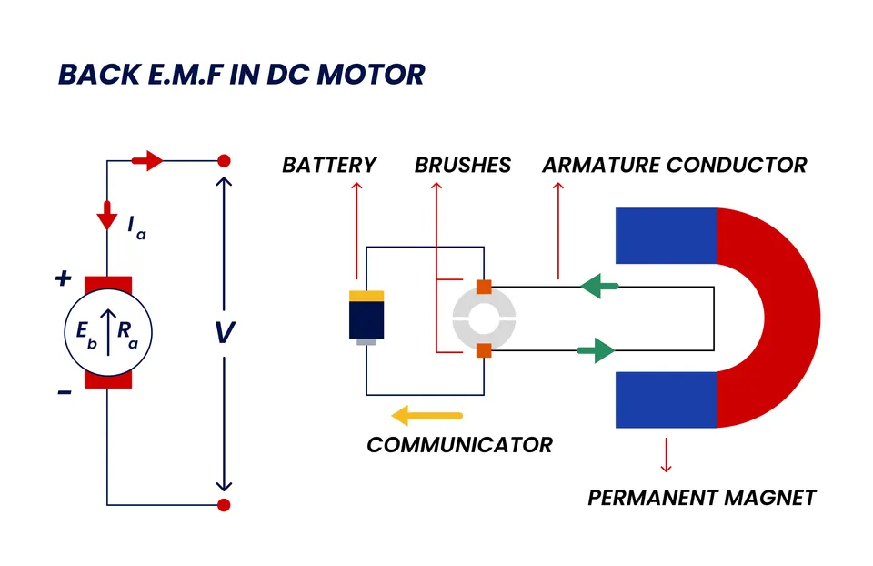
| What It Means | Rotational force generated by the motor | Revolutions per minute - how fast the motor shaft spins | How well the motor converts electrical energy to mechanical energy | Voltage generated when motor shaft rotates (useful in sensorless control) | Technique where the load motor returns energy to the system |
Sample Output Metrics You Can Measure
| Parameter | Rotational Speed vs Torque | Power Consumption | Motor Temperature | Voltage & Current | Efficiency Curve |
|---|---|---|---|---|---|
| Why It’s Useful | Shows Mechanical Performance under load | Understands electrical efficiency | Prevents thermal failures and Examine Durability | Tracks power quality | Visualize peak motor performance |
Expandability and Add-ons
You can take your dyno even further with:
- Arduino or Raspberry Pi integration for custom logging
- LabVIEW or MATLAB Simulink for advanced data visualization
- Battery emulators for real-world power source simulation
- Wi-Fi or Bluetooth modules for wireless monitoring
Conclusion
By using SOLO Motor Controller, you gain a high-performance, flexible, and user-friendly motor testing platform. It helps you build, test, and tune motors for robotics, EVs, automation systems, and education—all from your bench or lab.
Additionally, SOLO helps you to receive a motor performance curve in a very short time, which makes the motor evaluation faster and easier.
Products in this article
Related articles
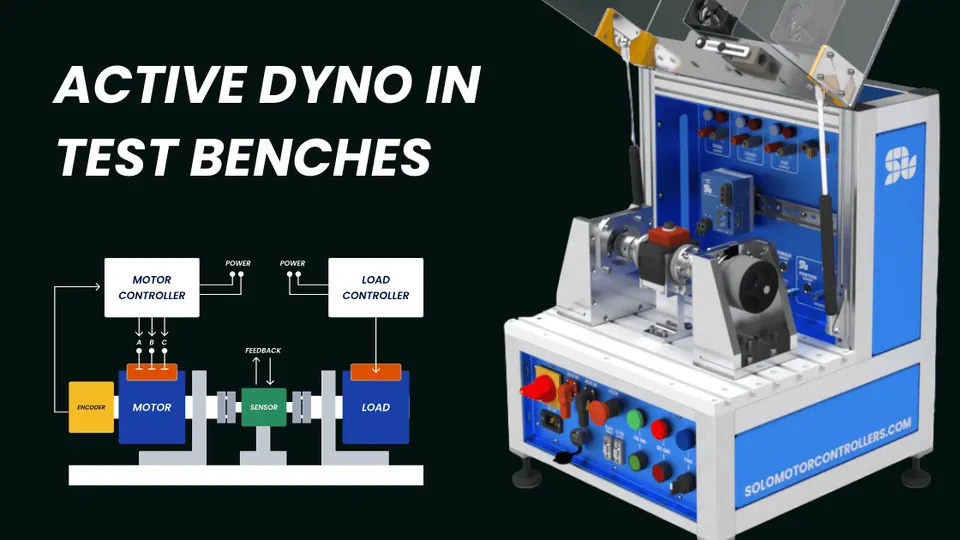
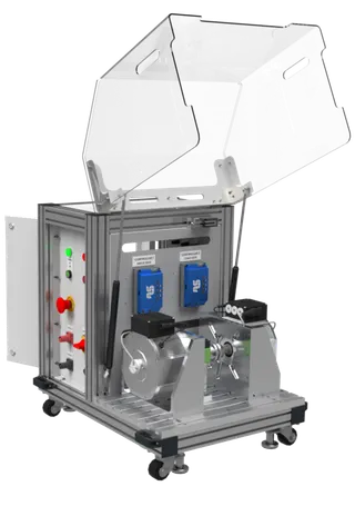
Active Dyno in Test Benches
Test EV, BLDC, and servo motors with precision using Active Dyno benches powered by SOLO Motor Controllers for bidirectional control and R&D.
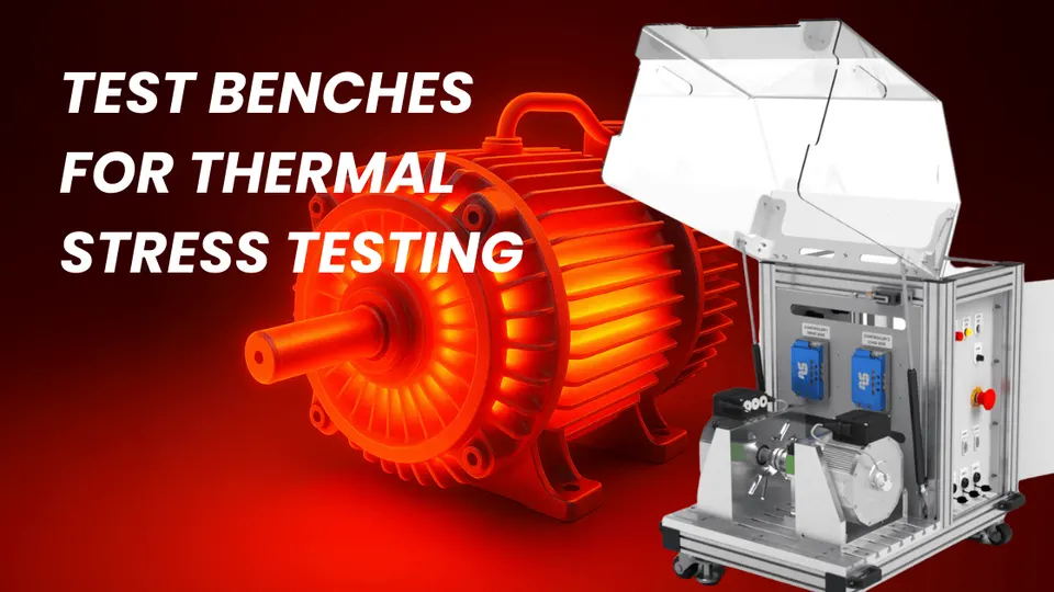
Test Bench for Thermal Stress Testing
Discover how thermal stress test benches improve motor reliability, safety, and efficiency by simulating real-world heat conditions.
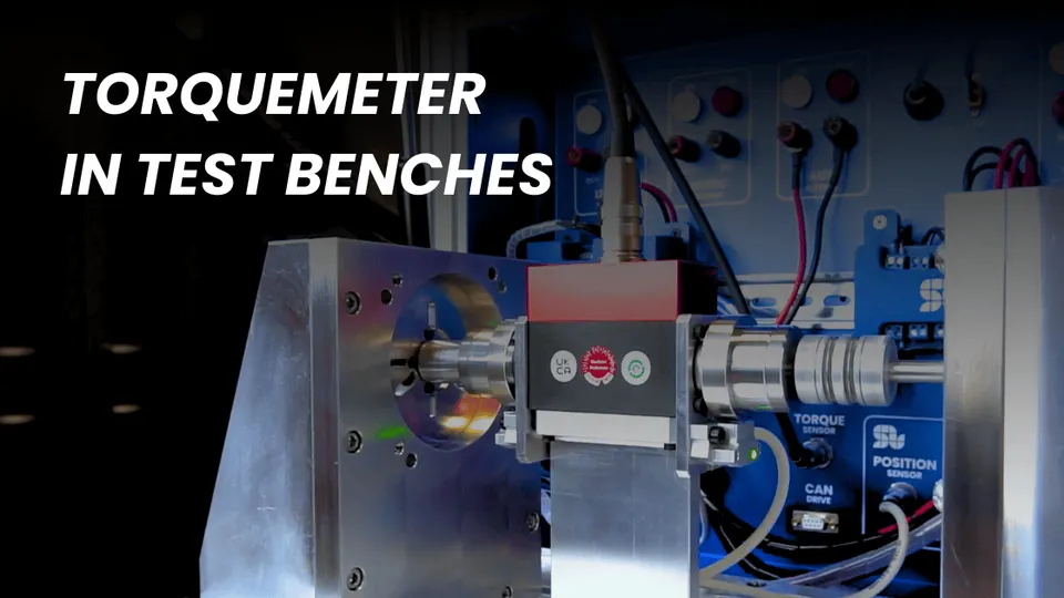
Torquemeter in Test Benches
Discover why torquemeters are essential for accurate motor testing and how SOLO Motor Controllers simplify torque-driven test bench setups.
