
Motor Thermal and Endurance Testing: Designing the Test Plan
Introduction
Most motor field returns trace back to heat or fatigue, not to a single dramatic fault. A winding that runs 15 C too hot loses insulation life fast, and a bearing that survives a short demo can still fail after a few hundred hours of real duty. A clean bench test that lasts ten minutes tells you almost nothing about either.
This guide shows you how to design a motor endurance test and a thermal test plan that catch those problems before your customer does. You will see how to set duty cycles, temperature limits, run-time, and the data to log, so the result is a number you can trust, not a guess.
Thermal vs Endurance Testing
The two tests answer different questions, and a good plan covers both.
A thermal test finds the temperature limits. You load the motor, watch the windings and case heat up, and record where performance starts to drop. The output is a clear derating point: the torque or current you can hold without crossing a temperature limit. Thermal tests are often short, an hour or two, just long enough for temperatures to settle.
An endurance test asks how long the motor lasts under realistic duty. You run a repeating load cycle for many hours or thousands of cycles, then look for drift and wear. The output is a survival number and a list of what degraded first.
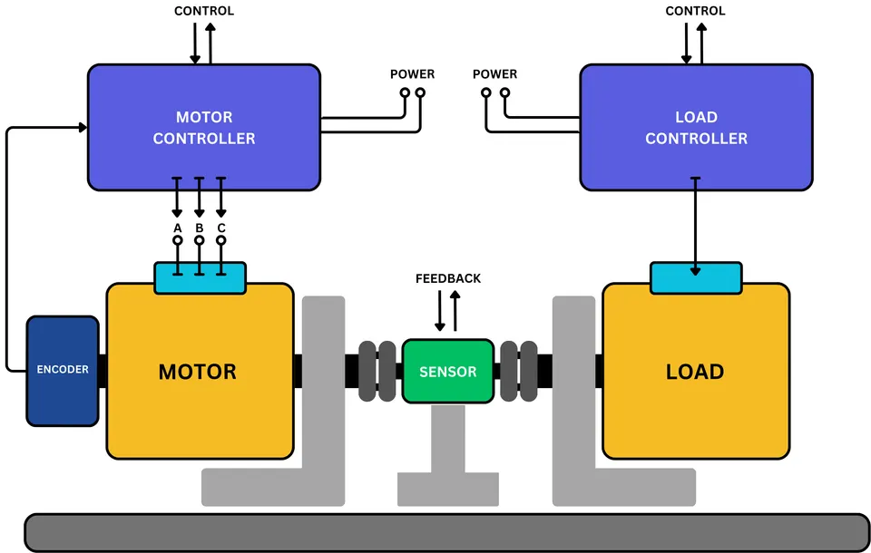
Both tests use the same tool: a bench that couples the motor to a controllable load and logs every channel over time. If you need the hardware side of this, our guide to the thermal stress test bench covers the setup, cooling, and instrumentation.
Takeaway: thermal testing finds the limit, endurance testing proves the motor lives at it.
Designing the Test Plan
A test plan is a small table that turns “test the motor” into something repeatable. Before you start, write one row per test with the load, the limit, the run-time, and the rule that decides pass or fail. Without that table, two engineers run the test two different ways and get two different answers.
Here is a test matrix you can adapt. Fill the numbers from your own motor’s data sheet and duty profile.
| Test | Load profile | Temp limit / derating point | Run-time or cycles | Pass / fail criterion |
|---|---|---|---|---|
| Thermal steady-state | Continuous torque, fixed speed | Winding ≤ insulation class limit | Until temp stable (1–2 h) | No channel crosses its limit |
| Thermal peak | Peak torque, short bursts | Winding ≤ class limit | 10–30 cycles | Recovers between bursts |
| Derating sweep | Step load up at fixed speed | Find torque at limit temp | Step every 10–15 min | Logs the safe continuous point |
| Endurance, real duty | Customer duty cycle, repeated | Stay below derating point | 100–1000+ h or N cycles | Drift within spec, no failure |
| Thermal cycling | On/off heating and cooling | Full operating swing | 100s of cycles | No solder, magnet, or bearing damage |
You do not run every row. Pick the ones that match your risk. A drone motor needs the peak and thermal cycling rows. A pump motor that runs at one steady point for years needs the steady-state and endurance rows.
Defining Duty Cycles and Load Profiles
A duty cycle is the pattern of load over time that the motor really sees. A motor that runs flat out for 30 seconds, then idles for 5 minutes, heats up very differently from one that holds half-load forever. Test the pattern, not just the peak.
Pull the profile from the application. For an e-bike that is the hill-and-flat road cycle, for a conveyor it is the start-run-stop cycle. If you only have a peak number, build a realistic envelope around it: peak torque, continuous torque, and the on/off ratio. As a rule, the continuous point drives thermal life and the peak point drives short-term stress.
Temperature Limits and Derating Points
Every motor has a temperature ceiling, usually set by the insulation class of the windings and the magnet grade. Cross it and you lose insulation life, or in the worst case you demagnetize the rotor. Your job is to find the load that keeps the motor safely under that ceiling at the worst-case ambient.
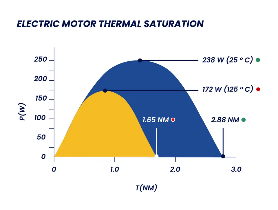
That safe load is the derating point. Torque and power both fall as the motor warms, because winding resistance rises with temperature and a hot magnet produces less flux. The chart below shows the same motor at 25 C and at 125 C: the hot curve sits well below the cold one. Test at the temperature your motor will actually reach, not at room temperature, or you will overstate what it can deliver.
Run-Time, Cycles and Acceptance Criteria
Run-time decides what the test can prove. A thermal test ends when temperatures stop rising, typically after one to two hours. An endurance test has to run far longer, often hundreds of hours or thousands of cycles, because wear shows up slowly. Match the duration to the claim: if you promise 2000 hours of life, a 10-hour run does not back it up.
Set the acceptance criteria before you start, in numbers. Define the maximum allowed temperature, the maximum performance drift (for example, torque must stay within 5% of the start value), and the hard stops that abort the run. Writing pass and fail in advance keeps the result honest and stops anyone from moving the goalposts after a marginal test.
Takeaway: a plan with fixed duty cycles, limits, run-time, and pass rules turns testing into a measurement, not an opinion.
Thermal Instrumentation
You cannot manage what you do not measure, and temperature is the hardest channel to get right. The reading depends entirely on where the sensor sits.
Sensor Placement (Winding, Case, Bearings)
The hottest spot is usually the winding, deep inside the motor, and that is the temperature that limits life. The best practice is an embedded sensor, a thermocouple or PT100, in the end winding during build. If you cannot reach it, instrument the case and the bearings, then learn the offset between case and winding for that motor so a case reading estimates the winding.
Place at least three probes: winding (or nearest reachable point), case, and a bearing housing. Bearings deserve their own sensor, because a failing bearing heats up locally before it seizes, and that early rise is a useful warning sign. Log the ambient temperature too, since every limit is relative to it.
Cooling: Forced Air vs Liquid
Cooling sets how much load the motor can hold during the test. Forced air, a fan over the case, is simple and fine for low and medium power. Above a few kilowatts the heat is too much for air, and you move to liquid cooling: a water or water-glycol loop through a cooled load or jacket.
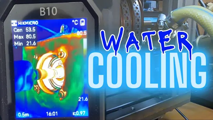
On a high-power bench the load itself becomes the heat problem. A 9 kW endurance run dumps real energy into the dyno, which is why those benches use a water-cooling loop sized for continuous duty, and antifreeze in the loop where freezing or higher boiling margin matters. Whatever the method, the rule is the same: the cooling must hold a steady, repeatable thermal boundary, or your temperature data drifts with the room.
Takeaway: put a sensor where the heat is, and size the cooling for continuous duty, not for the first ten minutes.
Running the Endurance Test
A long endurance run has to be automated. Nobody should sit and watch a motor for 300 hours, and a human cannot react fast enough when a limit is crossed at 3 a.m. The bench software runs the duty cycle in a loop, holds each load point, and logs every channel continuously.
Three things make an unattended run safe and useful. First, continuous data logging of torque, speed, current, voltage, and all temperatures, time-stamped so you can replay the run later. Second, automatic safety cutoffs: over-temperature, over-speed, and over-current limits that stop the motor on their own and record why. Third, a clean load that follows the profile, which is the dyno’s job. For how to size and pick that load, see the dynamometer side of the bench.

Takeaway: automate the cycle and the cutoffs, so the bench runs the test and protects the motor while you sleep.
Reading the Data
The raw logs are not the result. The result is in the trends you pull out of them.
Start with the temperature curves. A healthy motor heats up and then flattens at a steady value. A curve that keeps climbing means the cooling cannot keep up with the load, and that load is above the continuous rating. The settling temperature at each load point gives you the derating map directly.
Next, look for performance drift over the endurance run. Plot torque at a fixed current, or efficiency, against hours. A slow decline points to bearing wear, magnet aging, or insulation breakdown. A step change points to a discrete failure. Watch the bearing temperature for a slow upward creep, which is the classic early sign of a bearing on its way out. The goal is to catch degradation as a trend long before it becomes a failure.
Takeaway: read curves and trends, not single numbers, because the slope tells you what is wearing out.
From Test Plan to Production
The thermal and endurance plan does more than validate one prototype. It sets the limits your production line checks on every unit.
The derating point you measured becomes the safe operating limit in the data sheet and the firmware. The temperature where performance dropped becomes the over-temperature cutoff. The drift you saw over hundreds of hours tells you which channels matter most for quality control. End-of-line testing then runs a short version of these checks on every motor against the same limits. The long test you run once on a few samples defines the fast pass/fail test you run on thousands.
Takeaway: the endurance plan feeds the production limits, so design it once with production in mind.
How SOLO Runs Thermal and Endurance Tests
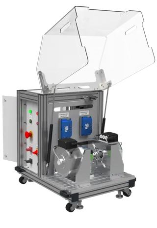
At SOLO we build test benches that support long thermal and endurance runs, with cooling sized for continuous duty and automated logging on every channel. High-power runs use a water-cooling loop on the load, so the bench can hold a steady thermal boundary for hours instead of drifting after the first few minutes. The software runs your duty cycle unattended, logs torque, speed, current, voltage, and temperatures over time, and trips its own safety cutoffs if a limit is crossed. Because we customize the bench to your motors, the sensor set, the cooling, and the test profiles match what you actually need to prove. You can see the current SOLO motor test bench and tell us the duty cycle you want to validate.
Conclusion
A good motor endurance test starts with a plan, not with a running motor. Write a test matrix that sets the duty cycle, the temperature limit and derating point, the run-time or cycle count, and the pass/fail rule for each test. Instrument the winding, case, and bearings, cool for continuous duty, and automate the run so the bench logs every channel and protects the motor on its own. Then read the curves and trends, not single numbers, to find the derating point and any slow drift. Done once with care, this plan also sets the limits your production line will use. If you want a bench tuned to your own thermal and endurance tests, the SOLO motor test bench page is a good next step.
FAQ
How long should a motor endurance test run?
It depends on the life you need to prove. A thermal test ends when temperatures stop rising, usually one to two hours. An endurance test runs far longer, often hundreds of hours or thousands of duty cycles, because wear shows up slowly. As a rule, the run should be long enough to back the life claim you put on the data sheet.
Where should I place temperature sensors?
Put the most important sensor as close to the winding as you can, ideally embedded in the end winding, since that is the hottest spot and the one that limits life. Add a sensor on the case and one on a bearing housing, plus an ambient probe. The bearing sensor is worth it, because a slow temperature creep there is an early warning of bearing wear.
What is thermal derating and why test for it?
Thermal derating is the drop in available torque and power as the motor heats up. Winding resistance rises and magnet flux falls with temperature, so a hot motor delivers less than a cold one. You test for it to find the safe continuous load at real operating temperature, not the optimistic number measured cold.
How do I automate a long endurance run?
Use bench software that loops the duty cycle, holds each load point, and logs every channel with a time stamp. Set automatic over-temperature, over-speed, and over-current cutoffs that stop the motor and record the reason. That way the run continues unattended overnight and stays safe without a person watching.
Tags:EnduranceTest BenchThermal
Products in this article
Related articles

Efficiency Mapping a Motor: Method and What It Reveals
How to build a motor efficiency map on a test bench: the measurement method, the torque-speed grid, and what the map reveals about a motor.
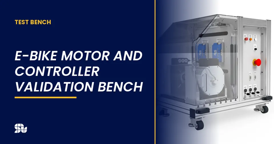
E-Bike Motor and Controller Validation Bench
How to validate an e-bike motor and controller on a bench: torque and cadence, assist profiles, regen and the metrics that matter for e-bikes.

Robotics Actuator Testing: Validating Motors for Robots
How to validate motors and actuators for robots on a test bench: torque density, backlash, repeatability and the metrics that matter for robotics.
